

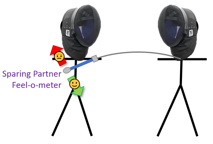
Ok, back to everyone’s favorite equipment safety topic: sword flex. I’ve seen this gaining more and more attention in the community, with regard to what we consider acceptable. But before we try to make (informed!) decisions we need data. And before we can collect data, we need to have a consistent protocol for said collection.
I’ve talked before about how I have issues with the current methods for measuring blade stiffness (Difficulties with SCA Flex Test and Buckling Test for Measuring Blade Stiffness). This criticism is centered on the ability of un-accounted for factors to influence the test results (SCA Flex Test) and the lack of procedures and knowledge of what we aren’t accounting for in the bathroom scale method. So now I have taken the time to run a whole bunch of tests, determine what is and isn’t important, and am proposing a procedure to be the standard for measuring blades going forward.
This is going to be a looooong article explaining all the testing I did to decide which factors are and aren’t important. So I’ll start with my recommended test procedure at the top for reference, which is the most important takeaway from this investigation.
Sword Buckling Load Test Procedure
1) Balance the sword vertically on the center of a scale, tip down. (I’m assuming most people would use a bathroom scale due to ease of access, but a higher precision package scale is better.) To ensure the sword is completely upright, nudge the hilt slightly side to side. You should see that it doesn’t have a preference for falling in any particular direction.
2) Curl your fingers around the crossguard from the underside, so you can pull down on the sword*.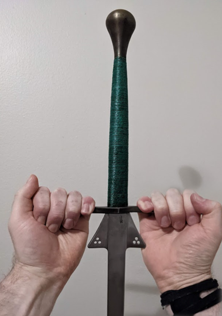
3) Pull down until you see a moderate lateral deflection in the blade. About 5-10 cm (2-4 inches) of bow. Record the force you see on the scale.
4) Let go of the sword and reposition slightly on the scale. Then repeat steps 1-3 to get a total of 3 measurements.
5) If the 3 measurements are within 0.5 kg (1 lb) of each other then take the average. If one is way off, keep testing until you get 3 that are close enough together.
There is certainly nothing revolutionary in this test procedure. It’s not exactly a result of any flashes of brilliance or inspiration on my side. It is simply the method I’ve found to be the most reliable and accessible way to establish a uniform procedure for blade testing. Based on everything you’re going to read below.
Conclusions At The Top, Like Dessert Before Dinner
In addition to the test procedure, everyone who wants to tl;dr this gets to skip right to the conclusions at the top!
- A sword can be roughly represented with the formula F = k * x + b, where k is a spring constant, x is the axial compression, and b is the buckling load. The spring constant can be approximated by k = 0.75 * b, assuming you are measuring in meters. Which means that the majority of the compressive force is coming from the buckling load (constant), and not the spring flex (increases the more you flex the blade).
- Adding a moment on the hilt, aka attempting to flex the blade by push-pulling laterally, will have a HUGE impact on the stiffness of the sword. By attempting to push the sword against the blade flex you can double the force of the thrust. By going with the sword flex you can reduce the force significantly, but I didn’t study that in depth. (Note to self, come back to this again in the future for more research.)
- There are many different ways a blade flex measurement could be conducted, and they will give radically different results.
- The procedure I have outlined, pulling down on the cross, gives an accurate representation of the blade flex and is one of the most precise ways to measure sword flex. I recommend that this be the official standard way to measure swords going forward, though I’m always open to someone else who can think of a better way. (Also there are open auditions for a name I guess, unless we want to settle for something like “Franklin Buckling Test”.)
- I still have some thinking to do with regards to how to account for blades that have sets in them. If you are testing existing swords that people own they are bound to have sets, which makes it not be a 100% accurate comparison to tests performed on new non-set blades.
And now we begin on the journey of how I verified the above procedure. I already warned you this is going to be a long ride, so here we go.
- Conclusions At The Top, Like Dessert Before Dinner
- Of Columns And Blades
- Experiment Setup
- First Thoughts
- Buckling
- Linear spring
- Y = mx + b
- Sword 2
- Buckling-Spring Proportionality
- Boundary Conditions
- Boundary Conditions: Positive Moment
- Boundary Conditions: Fixed vs Pinned
- Boundary Conditions: Negative Moment
- Offset Force Direction
- Replicability
- Conclusions
- Stuff For Nerds
Of Columns And Blades
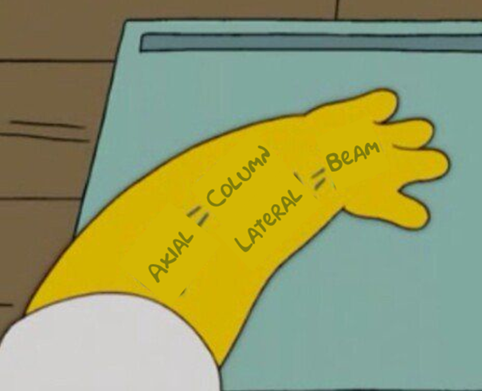
If you have a long thin object that is loaded laterally it is considered to be an engineering beam. Which is why beam calculation techniques have been used when looking at impacts from sword cuts. If you are loading a long thin object axially, with the forces directly along the long axis, it is considered an engineering column.
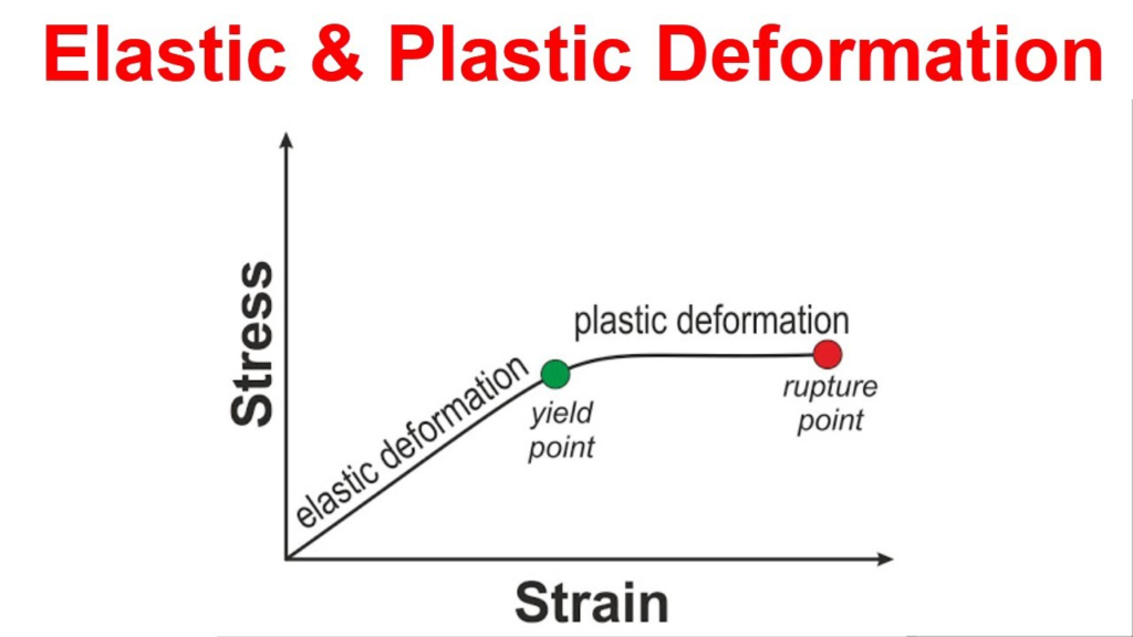
If you put something under compression or tension you’ll see that it will fail when the stress applied exceeds the yield stress of the material. But columns offer another failure mode: buckling. This is when the column deflects laterally at a load well below the yield stress of the material used.
And now we get to our first caveat: Modeling of conventional column buckling is all based on uniform columns. That means that the cross section does not change along the length of the column, which is something which is not true for swords. So how much of this modeling can we use? I don’t know. In broad strokes it’s going to be close, but there might be some discrepancies. This is why I wanted to do a whole bunch of different tests to determine which factors were important, and which are not.
The second thing to watch when looking at column buckling is that it is extremely sensitive to loading conditions. The assumptions of loading are based on pure axial loads, and the buckling will be extremely sensitive to forces not completely in line with the length of the blade. In addition any twisting forces acting on the hilt (from a tester’s hand) are significant.
Experiment Setup
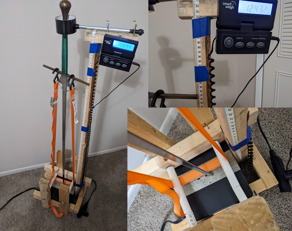
Given that I have lots of complaints about testing, how did I decide to do it? What I wanted to avoid at all costs was introducing any bending moment on the sword outside of the buckling from compression. So it was important to be pulling rather than pushing, because a push can introduce far more difficulties with direction of force applied. (Think of the relative difficulty of pushing a thread through a needle, vs pulling it through once you have it threaded.) Which meant pulling with a cable rather than pushing with a compressive load from the top. As part of this I also wanted to ensure said cable was pulling down along the centerline of the sword, and was free to rotate on the handle – so as to not be interfering with the rotation of the blade as it bent.
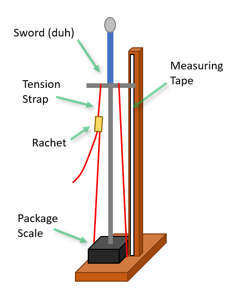
One issue with this setup is that the weight of the sword is annoyingly included in all the measurements. And it’s not as simple as just subtracting it from the final values. Thus far any horizontal based setups I’ve envisioned have kind of been a pain in the ass to work with, and I kind of gave up and just bit the bullet with a vertical setup including the sword weight.
Because of my concerns I initially started doing all my work using Newtons, the SI unit of force. This is how you do real physics, and would be more natural if I was going to be taking the sword mass into account. Fortunately based on some modeling I did it doesn’t seem that taking the mass into account is necessary (see the Stuff For Nerds appendix at the bottom) and I switched back to the more understandable data of raw kg as reported by my scale.
For most of the initial testing I used the same 3 swords I had readily available:
- [Sword-S] Sigi Forge: Shorty Feder, manufactured 2021. (I sure hope they did a good job on this one, as it’s already probably the most studied sword in HEMA.)
- [Sword-C] Chlebowski Swords: Blunt of Some Sort, manufactured 2013. I won this as a prize, so I don’t really know anything about it. The sword is a beast, weighing 1.73 kg (3.8 lbs) and feeling all that and more to swing.
- [Sword-F] Fabri Armory: Federschwert 125 cm Soft Flex, manufactured 2022. While it has the same dimensions and weight as a normal feder this is a ridiculously flexible sword. It, without exaggeration, makes the Sigi look like a stiff blunt.
All and all, this covers the potential range of swords quite nicely.
And, so ladies and gentleman, I introduce you to the Buckle Flex 3000™ in all its glory!!! (It didn’t have a name until I did an editing pass on the article and saw that I kept referring to it by different names, and needed to come up with something consistent to call it. Now I will repeat this ridiculous name obnoxiously.)
First Thoughts
After a bunch of headaches getting the Buckle Flex 3000™ exactly where I wanted it to be in terms of usability, I was raring to go and threw a sword on for the first test. Below is the data I gathered from two runs, forcing the sword to bend once in each direction.
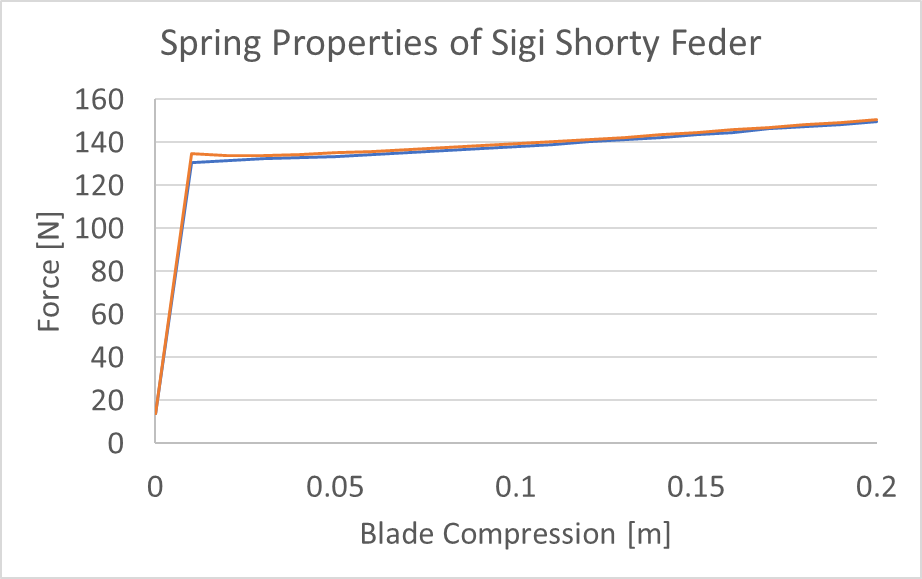
This is both neat to see, and a little boring. So let’s take a look at what it means.
Buckling
I’ve written about buckling before, and here is a quick run down. In an ideal column there exists a critical buckling stress, at which point the column basically collapses. In this way the column acts more like a brittle object, even if it’s made of ductile material like steel. If you load a beam it will sag and stretch before collapsing. A column will just go.
You can determine the critical buckling stress through a simple calculation using the cross section of the column and the material’s stiffness. Which is good to know, but not helpful given our swords don’t have constant cross sections. However we have a fancy new Buckle Flex 3000™ to determine it experimentally!
Linear spring
With buckling theory we expect to see the sword completely collapse after the onset of buckling, with the amount of force on the column not increasing significantly with more compression. However in my test data after the initial onset of buckling we see the force increase linearly with the displacement.
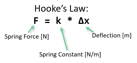
This is a relationship known as Hooke’s Law, which models spring behavior. Basically the force a spring exerts is directly proportional to how far you stretch it.
So, once buckling has occurred the sword transforms from a column into a spring. Cool. Given the complicated non-linear profiles of the blade cross sections, I was expecting and dreading a lot of nonlinear bending behavior. The fact that we see the swords behave like good little linear textbook springs eliminates a lot of future headaches I had anticipated running into.

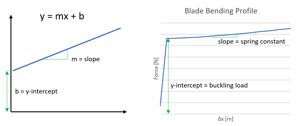
Y = mx + b
Another high school math refresher. A straight line has a formula of the form y = mx + b. Where x and y are the coordinates of any given points, m is the slope, and b is the y-intercept. And, conveniently enough, my sword bending data has both a y-intercept (the buckling load) and a slope (the spring constant). So it seems that treating the sword as an ideal spring with an offset buckling load is a good model going forward.
Sword 2
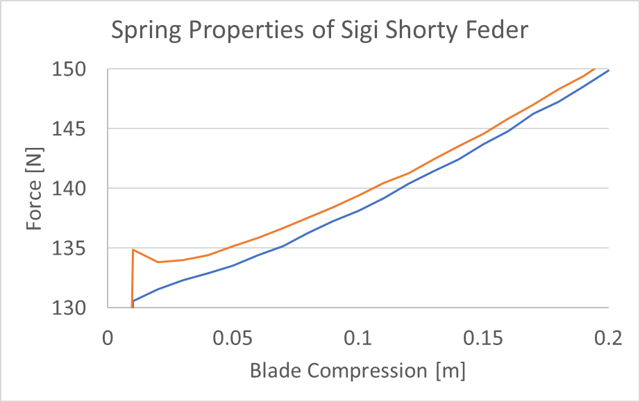
So, that was fun. Now I of course throw a different sword up there to test. And I notice something funny, after a little while the force stops going up with compression! That’s weird, so let’s look at the data.
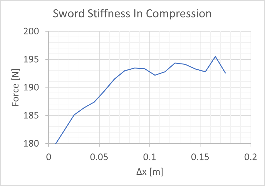
At about this time I start thinking that this graph looks awfully familiar…
And sure enough, my sword now has a feature that allows it to hook around parries.I literally captured the process of my sword taking a set on a force-displacement graph. Sweet.
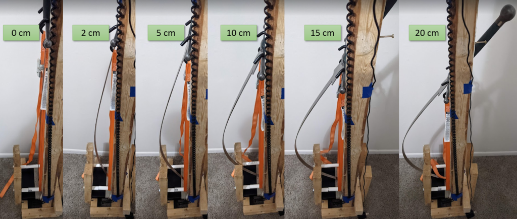
FYI, this is what the flex looks like for each amount of displacement, to give a perspective to these readings.
Epilogue: I did put a third sword on there and flexed up to 20 cm, and again I saw the linear spring behavior. So I think it’s safe to assume that F = k * x + b is a good approximation for sword force under axial compression.
Buckling-Spring Proportionality
The reason I constructed the Buckle Flex 3000™, which allows me to control displacement precisely, was to answer two questions:
- Is the force profile linear? As we saw in the previous section, that answer is yes.
- Is the spring constant (creating the force which increases as the sword bends) proportional to the buckling load? Sword profiles are all different, rather than them being the same basic blade but slightly thicker or thinner to change the stiffness. Therefore we can’t assume these numbers are correlated.
The answer to the second question will determine how extensive a test is needed to characterize a blade. If the two quantities are proportional then there is never a reason to test both of them. If you know that the buckling load indicates the spring constant then measure that, it is much easier. But if they are different it opens the door for theoretical discrepancies like what we see below.
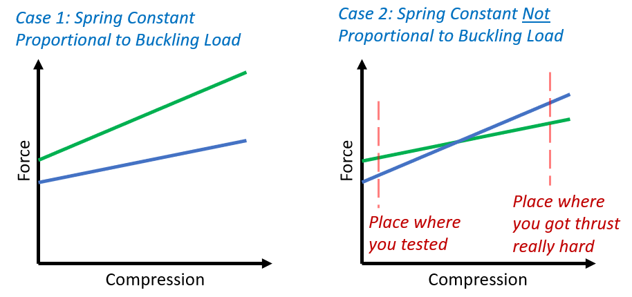
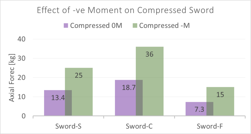
So, let’s compare how the blade’s buckling load relates to its spring constant. I’m going to compare the relationship between the two using K = c * B, where K is the spring constant, B is the buckling force, and c is the conversion coefficient. If they are perfectly proportional c will have the same value for every sword – Case 1 in the figure above. (Note that this makes c have the units of 1/meters, which is a little bit funky but about par for the course on how physical constants roll.)
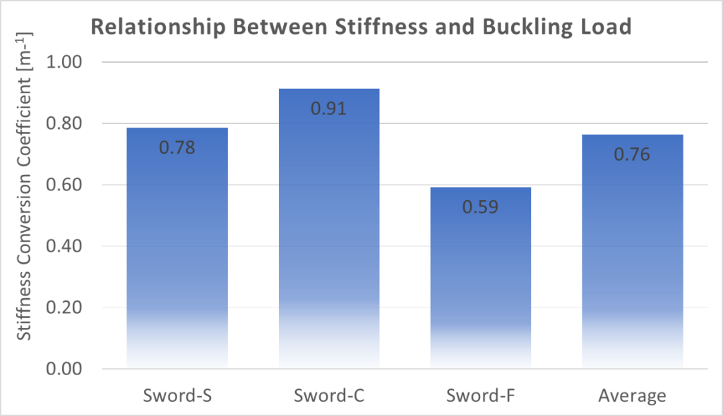
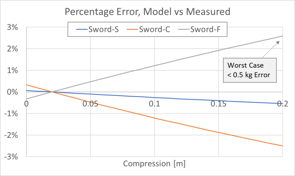
This… is not so great. But there isn’t a reason to give up all hope and resign ourselves to tedious blade characterization measurements. First of all is the fact that Sword-F is an extreme outlier in terms of sword design. It is ridiculously flexible. Assuming it’s going to conform to normal sword behavior is a bit iffy. It’s possible that with more testing we’ll see most swords falling into the .13 m-1 range between Sword-S and Sword-C.
The second is to consider just how much of a difference this makes. While these seem like big discrepancies in the correlation, we have to remember that most of the force contribution comes from the buckling load, with the spring constant being a far smaller contribution.
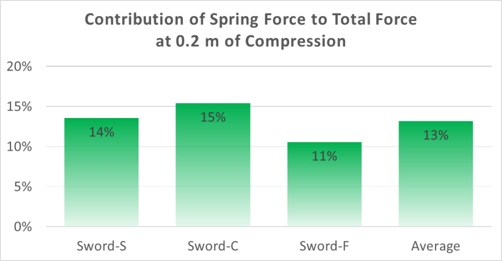
So if we were to assume the spring constant was (0.75 m-1) * (Buckling Load) instead of measuring it directly, we see less than a 3% error in total force at 20 cm of flex. Which works out to less than 0.5 kg in the stiffest sword I have access to.
So while this can certainly be understood better, I’m fairly confident I can now say that calculating the buckling load alone is sufficient for sword characterization. (Also I don’t want to test other people’s swords to 20 cm of flex, and risk putting sets in them.)
Boundary Conditions
When examining the buckling behavior we need to consider the boundary conditions, which I’ve brought up a bit when evaluating blade flex testing in the past. (Difficulties with SCA Flex Test and Buckling Test for Measuring Blade Stiffness).
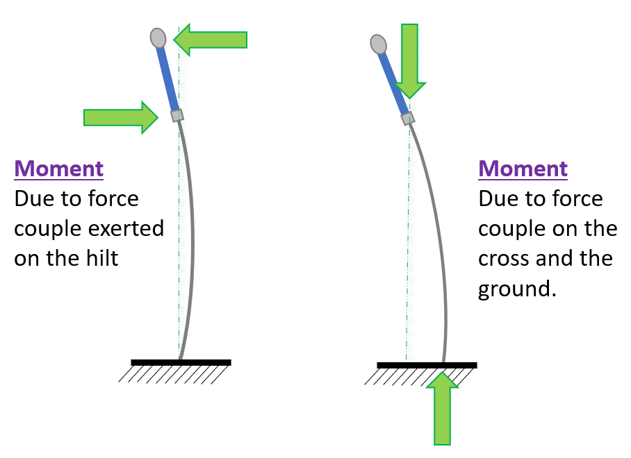
One of the biggest issues with people going to push on a bathroom scale is that they are introducing moments on to the sword, aka the column being tested for buckling load. And we also know that introducing a moment will significantly impact the buckling load.
A moment is any pair of forces which are equal in magnitude, opposite in direction, and not directly opposed to each other. This means that they make the object spin, rather than move. Torque is the colloquial way of describing a moment being exerted on something.
An important part of doing physics is defining your coordinate axis. If you’re doing serious lifting you need formal definitions, but in many cases we have a natural way of thinking about it. If I talk about distance between two fighters, we know that it’s horizontal distance between them. If I talk about compressing blades you know that the distance is along the long edge of the blade. However, moments often don’t have good natural orientations. So I made my own definitions.
- Positive Moment: One which is going in the direction of flex.
- Negative Moment: One which opposes the direction of flex.
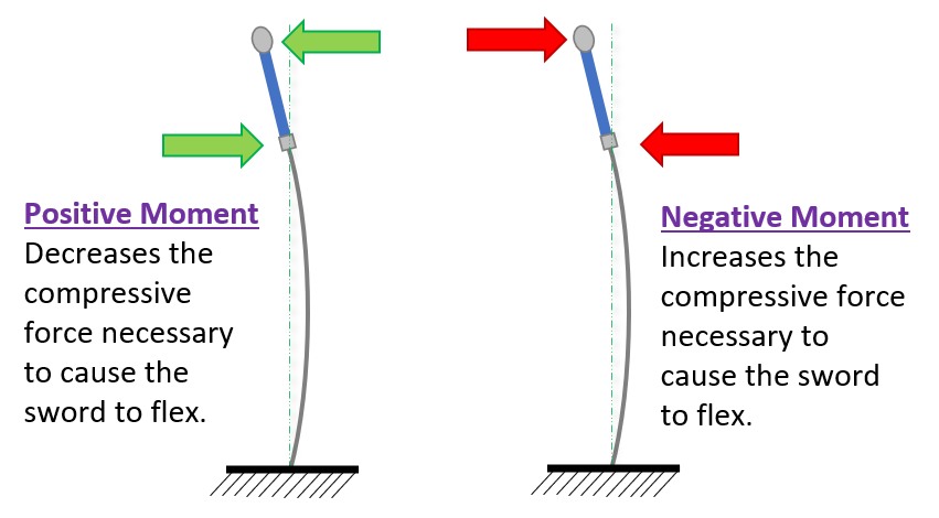
Note that the direction of the moment is relative to where the blade is flexing, rather than an absolute reference. If you change the direction of flex, a negative moment will all of a sudden be a positive one. With that nomenclature established, on to the first set of test conditions.
Boundary Conditions: Positive Moment
It is my suspicion that most flex tests performed have at least some positive moment applied to the blade. This leads to a measured force that is lower than the actual blade flex. Which isn’t actually a big deal, if it is consistent. The purpose of measuring swords is so we can compare them to each other, and even if the number isn’t the real physical number all that matters is that the numbers are all consistent relative to each other.
With regards to testing with a positive moment, I want to establish a range in which we expect measurements to fall. In addition I want to see how much of a difference pushing on the pommel vs pushing on the cross is. So for each sword I measured the buckling load in five different ways:
- [cross, 0M] – Buckling load of the blade, with no moment applied. This was done by flexing the blade to 3mm displacement with the Buckle Flex 3000™ .
- [grip, 0M] – Buckling load of the blade, with “no” moment applied. This was done by me holding the sword inverted, both hands close to the cross, and attempting to flex the sword in the way I see most people perform the test. While doing my best to eliminate all moments as I pressed.
- [grip, +M] – Buckling load of the blade, with moment applied at the cross. This was done by holding the sword in one hand, and seeing what I felt was the upper limit of inadvertent ‘cheating’ someone would realistically put in when trying to do a fair test.
- [pommel, 0M] – Buckling load of the whole sword, with “no” moment applied. This was done by me pushing straight down on the pommel and doing my best to introduce no moment.
- [pommel, +M] – Buckling load of the whole sword, with a positive moment applied. This was done by me holding the pommel/lower hilt with one hand and pushing down with what I felt was the upper limit of inadvertent ‘cheating’ someone would realistically put in when trying to do a fair test.
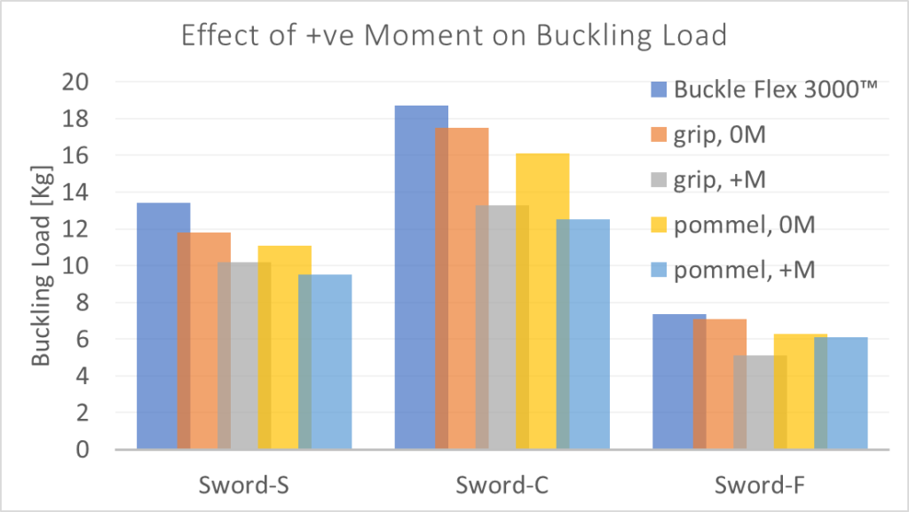
What we see here is more or less what I expected. Pushing on the pommel gets you a lower force reading than pushing on the cross. Being sloppy about how you get the sword to flex, rather than being diligent about pure axial loading, leads to lower force measurements. Instead of looking at it from an absolute point of view, let’s look at the difference in measurement approaches.
Below is a plot of the difference in buckling force when compared against the baseline data from the Buckle Flex 3000™. You’ll notice they are all negative, because they all result in a lower buckling load than the very controlled force applied at the crossguard.
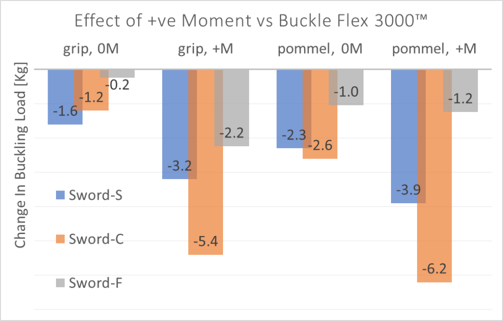
What we see is that adding a moment seems to have a much bigger effect than changing the grip position. Switching to the pommel can take off up to 2.5 kg of the sword’s flex reading, but adding a twist with the wrist can take off 3 kg or more – up to 4 kg if you do both!. When looking at this in relative terms it doesn’t show much of a different story, but it is pertinent.
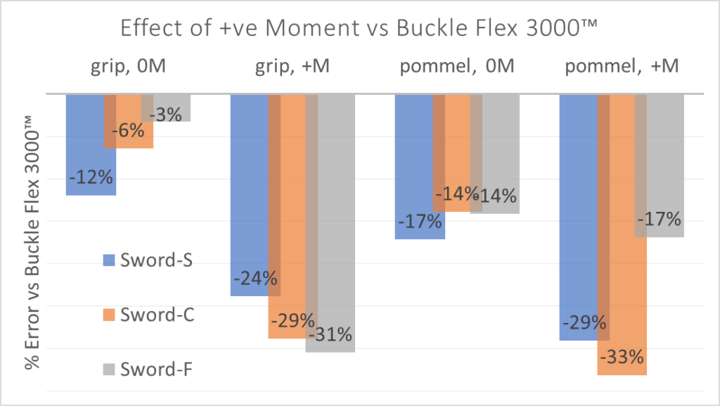
Long story short, the inconsistencies of just grabbing a sword and pushing on a scale are likely to make stiffer blades look more flexible than they actually are. While adding a moment might affect stiffer swords about the same from a percentage point of view, it’s a much higher number in terms of absolute kg. That’s how percent works. And if you don’t know how the test was performed it can make a stiff blunt look like a flexible feder.

Boundary Conditions: Fixed vs Pinned
Up until now we have been considering what is known as a pinned-pinned loading condition. This is loading the column so that the sword can freely deflect at both the cross and the tip, to facilitate the bowing out of the blade as it compresses.
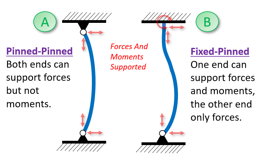
But what about fixed-pinned? This makes it so that you need a much higher flex before the blade begins to buckle. How much more? For an ideal column it’s 2x as much – determined through some fancy math I can follow if explained, but don’t ask me to recreate. (Though in practical engineering it’s treated more like 1.6 times.)
The fixed-pinned configuration is what would happen if you had a hand on the pommel of the longsword trying to keep it as straight as possible. So in order to quantify this I modified my test procedure. Instead of going down by a centimeter or two between each reading I was crawling by the smallest possible nudge I could. And at each point I would hold the cross and pommel and push laterally, to see if I could get the blade to straighten. If I managed to succeed I would then give the strap a little tighten, and see what the maximum loading I could achieve was. If we translate this into the nomenclature about moments we used above, I added a negative moment to try to keep the blade straight. (The textbook difference between a fixed and pinned connection is the former can exert a moment, and the latter can not.)
Note that forcing a blade to keep straight will increase the force far beyond what a flexed sword can achieve, no matter how hard you press. Smashing into a sword harder and harder will just cause it to flex/collapse even more, but not produce much more force. Having the blade be locked straight will be the biggest force multiplier you can get. (Which is why a half-sword thrust can generate exponentially more force than a normal thrust. If you lower the effective blade length in half you increase the buckling load to 400% of the normal value.)
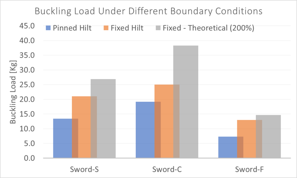
You can see that trying to fix the hilt increases the buckling force significantly. Why are the swords lower than the theoretical? I can think of three possible explanations:
- The fixed end was the end closest to the cross, aka the stiffest cross-section of the sword. We would already expect this to have the lowest amount of bending, and thus fixing this end doesn’t do as much to the sword overall. If we instead fixed the tip the effect would probably be much greater. (Though that’s impossible, as to fix the tip we would need some way to fix it. Which is kind of hard given that there is nothing beyond the tip to anchor, by virtue of it being the end of the sword by definition.)
- I’m just doing the “fixing” with my hands and not on a vice. This is a more realistic case, representing the “worst case” we could expect in sparring. But also not providing as much of a rigid anchor and we would expect somewhat of a decrease in effectiveness of the fixing.
- Even though I’m trying to keep the forces aligned to the best of my ability, it isn’t perfect. There is a quantity defined as “slenderness ratio” which basically describes how strong a shape is against bending vs how long it is. Higher slenderness means longer and thinner. Which makes it, as you would expect, more likely to buckle. From an engineering point of view a slenderness ratio over 100 is extremely sketchy for a column. A sword is more in the ballpark of 1000. Which means that expecting to see “ideal” buckling behavior is unrealistic.
Boundary Conditions: Negative Moment
In the last section I looked at how changing the boundary conditions could affect the buckling load of a sword, and how keeping the hilt fixed could produce far higher forces than from compression alone. But that is not the worst case for sword loading!
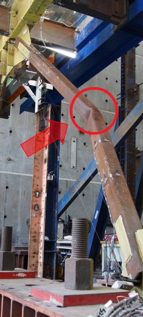
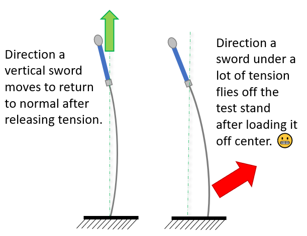
In construction you often need to put a lot of force on something, and having special (and costly) power equipment on hand isn’t exactly practical. So if you have to do something like say, move a wall that isn’t quite straight, you can use a technique like a bow brace. This works by bending a piece of wood and then fixing the ends in place. This puts the wood under a lot of tension, but the real trick is when the flex is forced out of the makeshift column. By pushing laterally on the bow in the middle of the brace (usually done by hammering in another piece of wood against it) the lateral force is transmitted into axial force along the length of the brace, and an extreme amount of force at that!
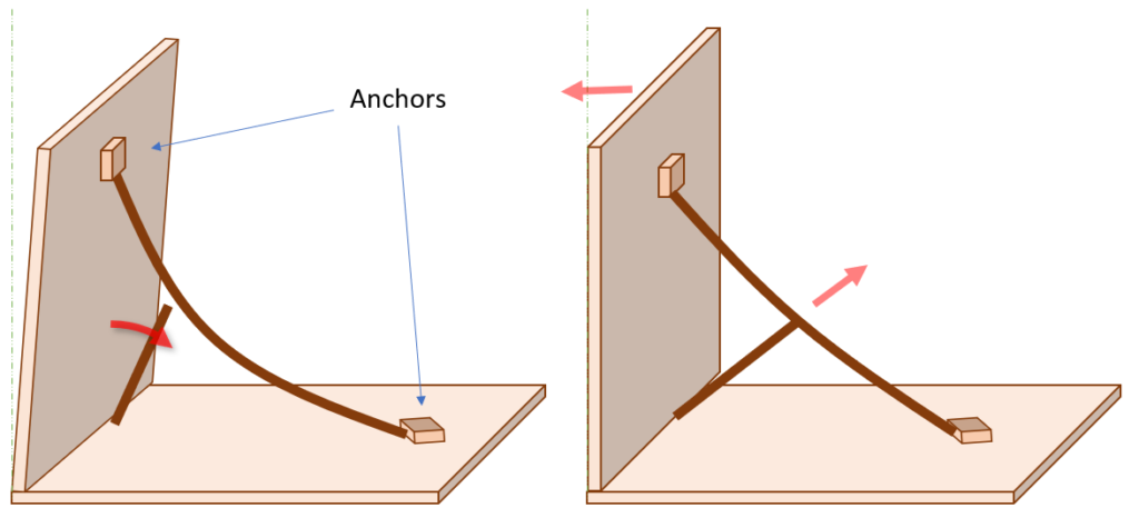
So what if I made a bow brace out of a sword? I flexed my Sigi Shorty to about 13 kg and then tried to see how much force I could generate by pushing laterally on the blade. The result? I don’t know. Because my scale stops measuring at 50 kg.
But that’s not super realistic, and would basically only happen if you thrust enough to generate a large blade flex, then switch to half swording and crank on the blade against the direction of flex. (Though who knows what edge cases come up with the thrust-ey’s arm pushing against the side of the blade.) What is probably much more common is force acting on the hilt as the thrust is in progress.
What is the scenario for this? When a negative moment is applied on the sword hilt after the blade has already flexed. (Remember above I defined a negative moment as a torque which opposes the direction of blade flex.) If there is only a small deflection the blade will probably snap to flexing the other way, with the same moment now being a positive one which helps the blade flex.
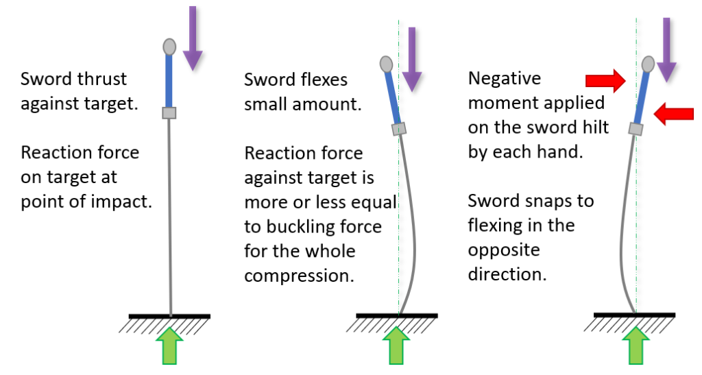
If there is a large deflection the sword can’t snap to flex in the other direction. Instead the force on the target will just be increased significantly.
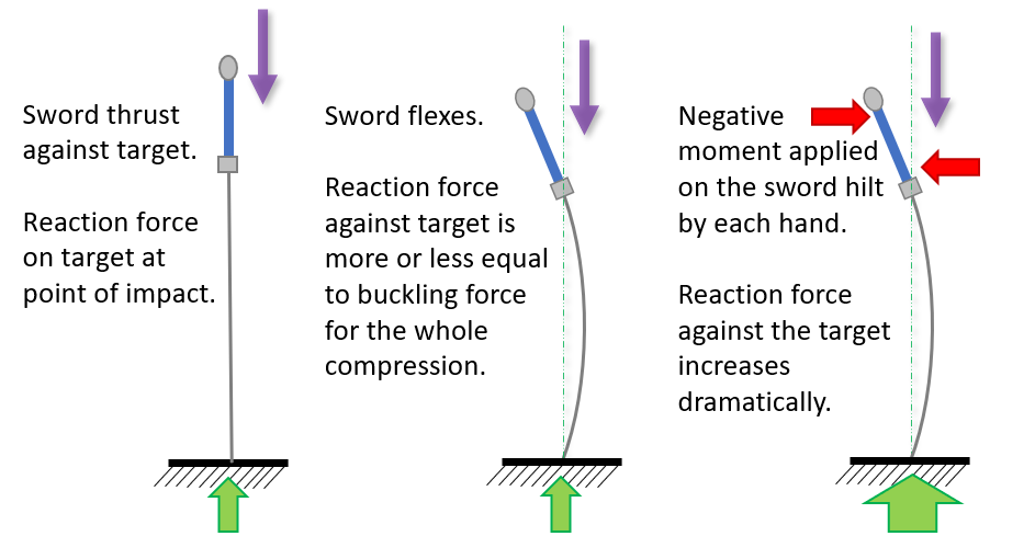
Testing this was a bit wonky because I wasn’t really set up to do it. First of all I had no real way of controlling the moment I was exerting on the blade, so I couldn’t be sure that I was being consistent for all swords. Second of all I don’t know what is a realistic moment to be applying. Nevertheless I performed the test to the best of my ability, trying to torque on the hilt of each sword to a level I thought was high, but realistic under high intensity sparring conditions.
It looks like a surprisingly consistent 200% of the normally loaded force. But doing it the way I did is a VERY subjective test, and even though I tried to be consistent I’m not exactly working with machine level precision on my hands. The main outcome of this test is that:
- Normal flex testing seems to be representative of the stiffness when a negative moment is applied after the sword flexes. So blades don’t need to be characterized this way. Though a more rigorous confirmation is certainly warranted.
- Applying a negative moment after the blade has begun to flex can up to double the thrusting force of the sword. I would suspect in most cases the moment applied at the sword hilt is neutral to positive, however when designing safety systems the worst (reasonable) case is what is considered.
Which leads to this implication: What the person thrusting does in terms of bending the blade to go with, or against, the flex of the sword on impact can up to double the impact force that the blade is exerting. This is probably an interesting conclusion from a coaching point of view that is significantly out of scope of this article.
Offset Force Direction
The last thing to check off my list is the influence of pushing on a blade not straight down. I’m going to use the convention of negative and positive offsets to keep track of my measurements, with the negative being the tip positioned back away from the direction of flex, and positive with the tip pushed forward in the direction of flex. As always, a picture is worth a thousand words.
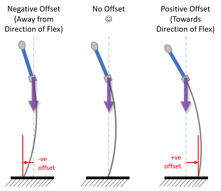
The more physics inclined might be asking, “by offsetting the force aren’t you just putting the ground reaction force along a different line of action, thus instigating a moment? And you already tested for the influence of moments earlier?” Good questions; let’s catch up the rest of the class.
So moving the sword out of alignment is, in fact, adding a positive moment. And I can guarantee you when I was trying to be bad at measuring (in the +ve moment section above) I was holding the sword crooked to some degree. On paper even a relatively minor misalignment of a column can decrease the buckling load to a quarter its original value.
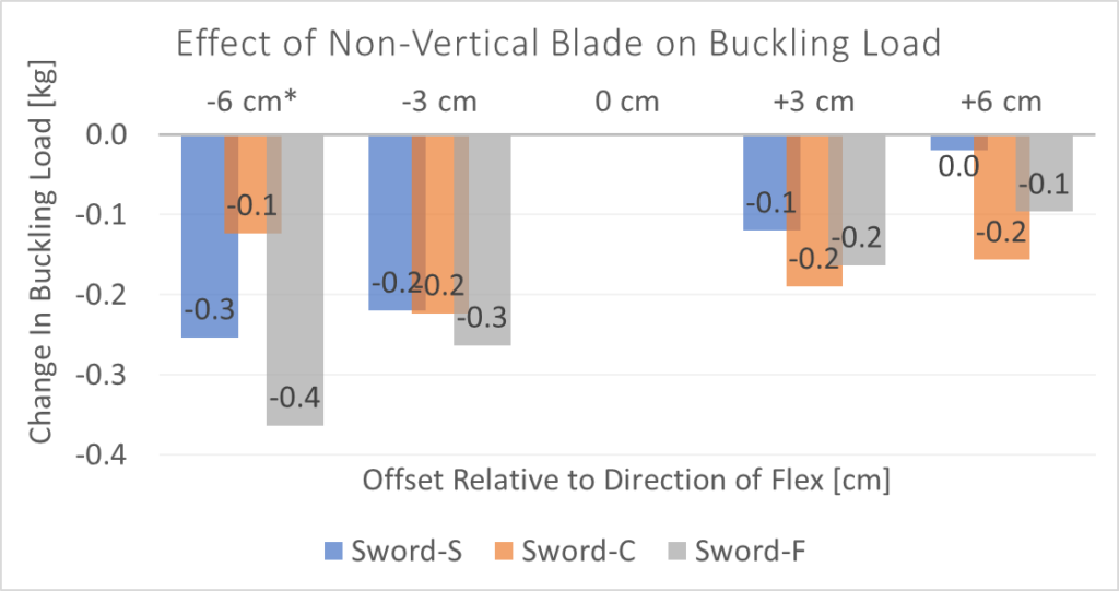
This shows that we do get some noticeable effects by moving the sword off center, but not as bad as I feared. If you want to be rigorous when classifying blades it’s not so good. But I feel it is mitigated by the following factors:
- If you’re careful about ensuring the sword is properly balanced up and down you can be within 1cm on either side without a particularly high degree of skill.
- Most swords are classified with no greater resolution than 0.5 kg. So realistically you will introduce an error of less than half of this if you are testing smartly.
With that I’ll close the book on off-angle blade deflections. I think this is another case of the sword being like a column from a hypothetical point of view, but the blade being so thin that getting the ideal loading for column buckling is plain impossible. Which means, conversely, that these errors are mostly present already and introducing more of them has less of an impact.
Replicability
So now that I think I have tested all the possible important factors, I think I have a procedure in mind.
- Balance the sword vertically on the center of a scale, tip down. (I’m assuming most people would use a bathroom scale due to ease of access, but a higher precision package scale is better.) To ensure the sword is completely upright, nudge the hilt slightly side to side. You should see that it doesn’t have a preference for falling in any particular direction.
- Curl your fingers around the crossguard from the underside, so you can pull down on the sword.
- Pull down until you see a moderate lateral deflection in the blade. About 5-10 cm (2-4 inches) of bow. Record the force you see on the scale.
- Let go of the sword and reposition slightly on the scale. Then repeat steps 2-3 to get a total of 3 measurements.
- If the 3 measurements are within 0.5 kg (1 lb) of each other then take the average. If one is way off, keep testing until you get 3 that are close enough together.
With that figured out I’m off to grab a few other people’s swords and see how consistent and accurate the measurements are using this method. Note that just about all of these had some amount of set in the blade. You’ll also recognize the last 3 as ones that have been tested over and over again in this article. (The order is not representative of anything other than what order I happened to pick them up off the pile to do the first test.)
| Maker | Model | Year Manufactured |
| Krieger Amory | Harbinger | 2022 |
| Ensifer | Light | 2019 |
| Sigi Forge | Concept (Lichty) | 2021 |
| Arms and Armor | Fechterspiel | 2019 |
| Regenyei Armory | Short | 2017 |
| Fabri Armorum | 125 cm Feder, Soft | 2022 |
| Sigi Forge | Shorty | 2021 |
| Chelbowski Sword | Blunt | 2013 🙂 |
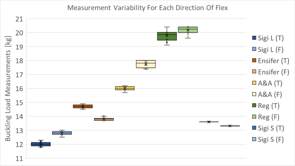
For each sword I took data with three testing methods: pushing the pommel down as accurately as I could, pulling on the cross using the procedure I described above, and using the Buckle Flex 3000™ to a compression of 2 cm. I took 10 measurements of each method, taking the blade off and repositioning between each to make sure all the data points were independent pieces of data.
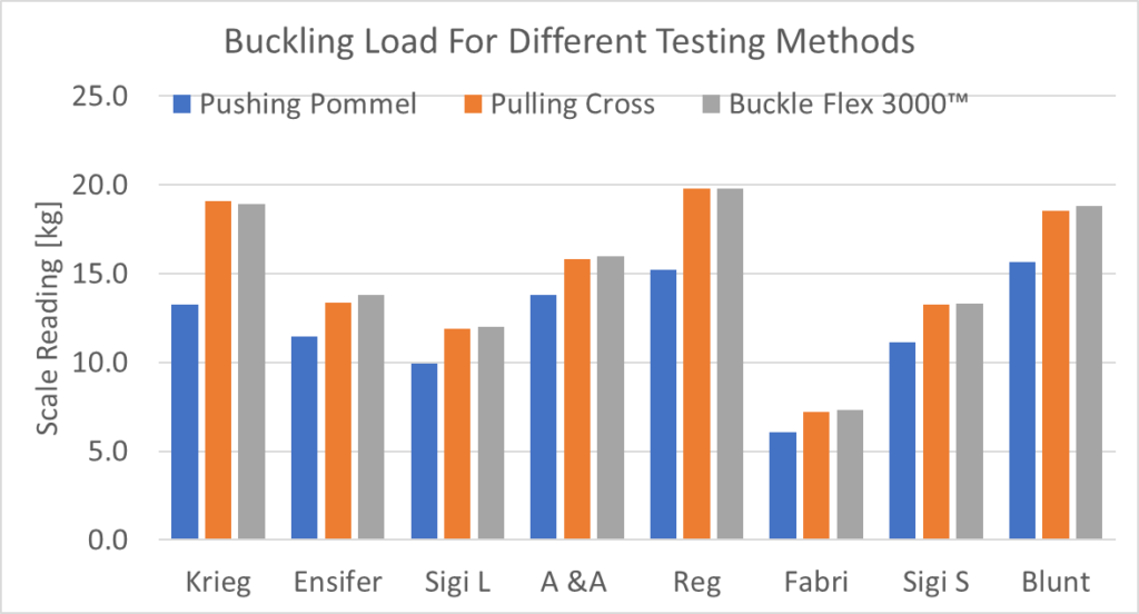
The pommel pushing shows a much lower buckling load than exerting force at the cross, which is more or less what you expect. The procedure I outlined above seems to have pretty good alignment with the more accurate test method, so let’s compare in a little more detail.
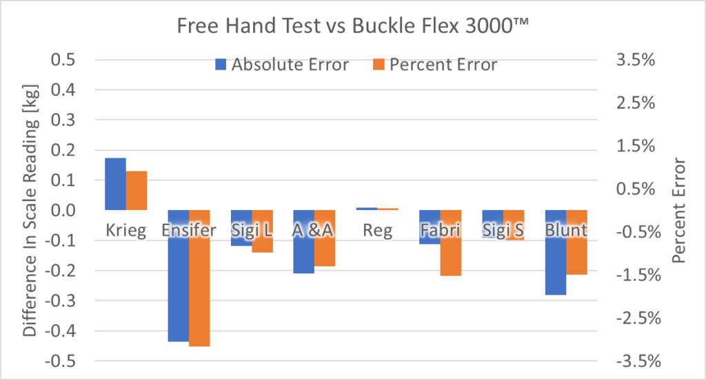
It is pretty close, with there being less than 0.2 kg difference between measurement methods. The big outlier is the Ensifer blade, though that one had a really nasty set in it. Which could have affected the measurement. (I’ll talk more about sets in the conclusion.) Overall I’m pretty happy that the measurement procedure is getting close, given how easy to use and widely applicable it is.
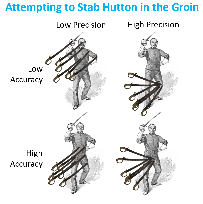
And finally, how precise is each method? Remember that accuracy is how close you are to the correct value on average, and precision is how close your measurements are to each other. Up until now I’ve been showing you average data, which is kind of meaningless if individual measurements are all over the map. Because what we want are repeatable test results.
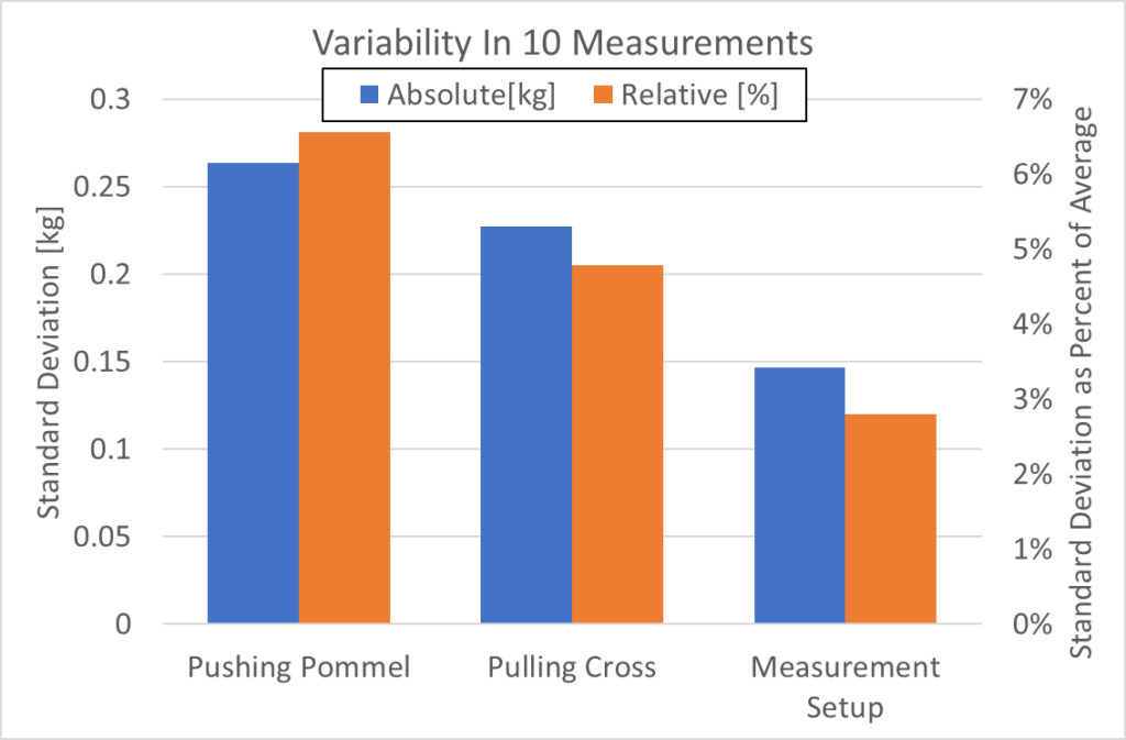
All told it’s more variability than I would like in measurements, with the cross pulling method showing about 0.2 kg standard deviation on most swords. But my “high precision” Buckle Flex 3000™ isn’t that much better, with a standard deviation of 0.15 kg. It is refreshing to know that 1 standard deviation using my test procedure is on average 5% error on the measurement, which is relatively good for an at-home test. By taking a few samples we can be fairly confident we are within the 1 standard deviation range, and thus have no less than 5% measurement error on the data we have collected.
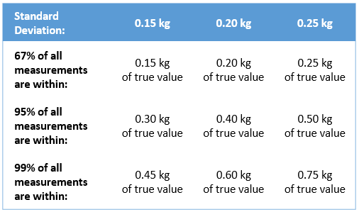
Also, if you still aren’t clear on the difference in accuracy and precision:
Conclusions
And here we are some 5000+ words later. (If this was back when I was keeping to a weekly schedule you could expect this split into 4+ different articles.) The results of all of this:
- A sword can be roughly represented with the formula F = k * x + b, where k is a spring constant, x is the axial compression, and b is the buckling load. The spring constant can be approximated by k = 0.75 * b, assuming you are measuring in meters. Which means that the majority of the compressive force is coming from the buckling load (constant), and not the spring flex (increases the more you flex the blade).
- Adding a moment on the hilt, aka attempting to flex the blade by push-pulling laterally, will have a HUGE impact on the stiffness of the sword. By attempting to push the sword against the blade flex you can double the force of the thrust. By going with the sword flex you can reduce the force significantly, but I didn’t study that in depth. (Note to self, come back to this again in the future for more research.)
- There are many different ways a blade flex measurement could be conducted, and they will give radically different results.
- The procedure I have outlined, pulling down on the cross, gives an accurate representation of the blade flex and is one of the most precise ways to measure sword flex. I recommend that this be the official standard way to measure swords going forward, though I’m always open to someone else who can think of a better way. (Also there are open auditions for a name I guess, unless we want to settle for something like “Franklin Buckling Test”.)
- I still have some thinking to do with regards to how to account for blades that have sets in them. If you are testing existing swords that people own they are bound to have sets, which makes it not be a 100% accurate comparison to tests performed on new non-set blades.
Stuff For Nerds
Appendix 1: Blade Sets
When I was testing the big pile of swords it shouldn’t be a surprise that most of them have sets. Keeping your swords in pristine condition is a nice side effect of being too injured to swing them, but inevitably most swords available to test will be a little worse for wear.
First of all, yes you can see the flex in sword test data. As part of the procedure I was taking the sword off and repositioning every time, which also meant flipping the blade around and flexing it the other way. And I noticed I started getting some serious discrepancies in measurements between flexing in the two directions.
You can easily see which direction a blade has a flex in, the one with the lower buckling load. And it’s somewhat pronounced, about a 1kg difference between the two.
For the comparisons in this article I always used the lower flex version. After all, when testing by hand the blade is always going to flex in the direction with the lower buckling load. So comparing the accuracy of the measurements is still valid.
But what about comparing swords with sets to swords without sets? It’s hard to tell without taking a new sword, testing it, putting a set in it, and then testing it again. Which I don’t have a bunch of volunteers for (as you’d need to do it across multiple swords to get a baseline). Other than that, one would think you can just average between the flex going both directions, but just because you can take two things to average doesn’t mean it’s good.

More investigation needed, but given we are only talking of about a 0.5 kg discrepancy when testing known damaged swords I don’t think it’s the end of the world for now.
Appendix 2: Blade Energy
You may remember that energy = force * distance. Which means that as I am applying force to the blade to compress it I am expending energy, which is then stored as potential energy in the blade. More specifically it is stored as energy in the internal molecular structure of the steel, as the intermolecular bonds are pulled like elastics. (Why Does my Gear Crack in Half?)
Using calculus we see that the energy stored in a spring is the integral of the force, or in other words it’s the area under the force-displacement graph. (E = ½ * k * x^2, if you care.) This gives us the opportunity to see the energy going into rearranging my sword’s molecular structure on the test where it took a set.
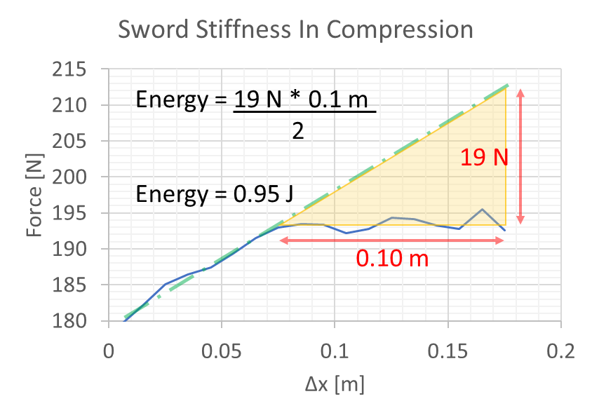
The total energy stored in the blade is a little more complicated because we have a column + spring setup. If F = kx + b then E = ½kx2 + bx. Which means that once you know the blade’s bending parameters you’re able to calculate how much energy is in a blade compressed to any given amount. (if you want to complain about the lack of +c at the end, you can go home now. Nobody likes you.)
While marginally interesting we can also combine with the formula for gravitational potential energy: E = m*g*h. Or, more colloquially, the gravitational potential energy of an object is proportional to its mass and elevation multiplied by the force of gravity. Or, in other words, we now have everything we need to calculate how high a sword can fly given the amount of compression the blade has undergone.
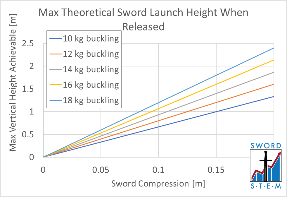
(If you’re wondering why the graph is linear, the contribution from the ½mx2 term is minimal, and you can simplify the formula to h = (b*x)/mass. I just assumed a 1.5 kg sword. I’ll be sure to be more specific if I ever test this for real.)
Appendix 3: Adjusting For Weight
I was concerned about the weight of the blade being a source of error in the measurements, as all of the weight is recorded on the scale but only part of it is fully bearing on the blade, thus introducing flex. Originally I planned to correct for this in measurements, and I did the following for the first few data plots I collected:
- Calculated the Centroid of all the cross sectional Area Moments of Inertia. Which I believe should be the point where we see half of the flex happening on each side, based on my gut feeling that’s how it should work. (I have never seen any literature on anyone doing something like I’m doing.)
- Determined what percentage of the sword’s mass was below this point, and thus was registering on the scale reading but not actually contributing to bending. This was really difficult, because there is no way to determine it directly. I had to take the cross sectional measurements I took and use the volume and density of steel.
- Calculate how much error this force was adding into the calculations.
You would expect that an offset would introduce more error in a more flexible sword, which was the case. But the total error was only 3% for the flexible and 1% for the stiff. This makes sense, because the area that needed to be discounted was the area closest to the tip. The part of the sword with the smallest amount of steel.
This was a HUGE pain in the ass to do, and once I saw how small the error was I decided I wasn’t going to worry about it ever again. (I realize my method is also not 100%, but doing anything else would be even more work for even less added precision.)
Appendix 4: Coming Up Next Time
Wow, you made it through all that. Just a spoiler for upcoming test data: cranking up sharp swords into high-tension springs is scary as hell.