

Calculation of the Moment of Inertia can be a very, very, very difficult task for an object of any complexity. Generally speaking we have four options available to us:
|
Don’t remember what the Moment of Inertia is? Do some catch up: Center of Percussion? Vibration Node? Balance Point? What does it all mean? |
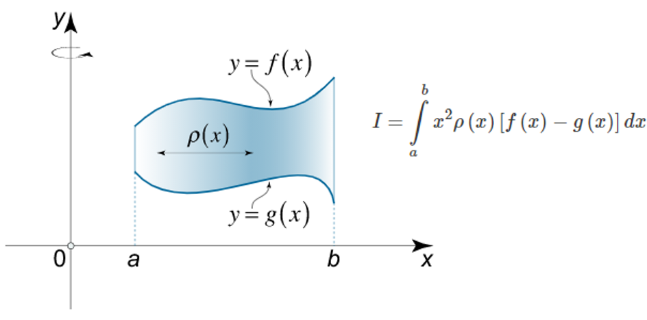
Option 1: Complicated Math
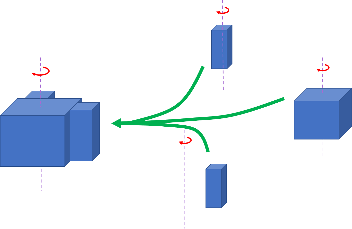
Option 2: Puzzle
The math for calculating the moment of inertia is complicated. Most of the time it is accomplished by taking pre-derived Moment of Inertia formulas and putting them together like a puzzle. For instance, imagine you are trying to calculate the Moment of Inertia of a cube with a rectangular hole in it. You don’t want to do math, but no one has prepared that exact formula for you.
Instead you break the problem into a bunch of simpler components (ones that have formulas), calculate the Moment of Inertia of each, and then add them all together.
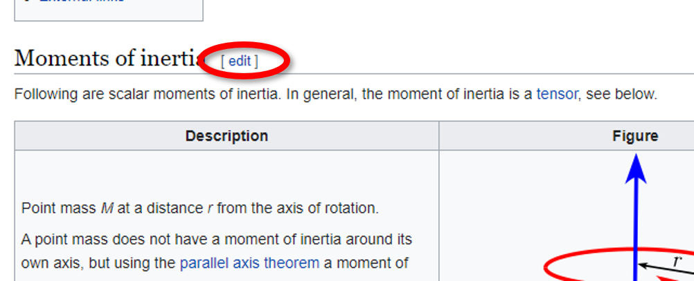
This would be like calculating the Moment of Inertia of the blade, cross, grip, and pommel separately and adding them all together. Unfortunately the wikipedia page listing Moments of Inertia doesn’t seem to have entries for sword cross guards and blades.
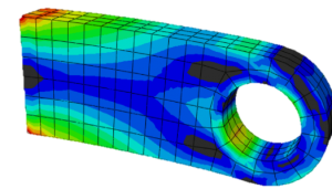
Option 3: Computer Magic
“Numerical Methods” is engineer-speak for “screw the math, just let the computer brute force a solution”. Essentially the shape is broken into a ton of very small, and solvable, elements, and the computer chews through the math. This technique is known as Finite Element Analysis (FEA) and it trades doing clever math (something that computers are bad at) for doing a ton of simple math (which computers are very good at). If you have ever seen a contour plot of stresses or temperature analysis on an object, you are looking at FEA results. In the shape below you can see the small pieces the shape was broken into by the computer.
There are two difficulties with this from a HEMA point of view:
- This type of software is expensive. Good luck on that unless you happen to be borrowing a license from your school or place of work.
- You need very precise measurements of the sword. Not only would you need a good 3-D model generated of the complicated blade and hilt geometry, but also of the tang inside the grip.
Option 4: Move it and see what happens
Given that static testing is impossible, and calculating the Moment of Inertia is very difficult, the solution is to move the object and see what happens. The Moment of Inertia is the resistance to rotation. So if a known torque is applied, and the rotation observed, we can then calculate what the Moment of Inertia was.
In the past Vincent Le Chevalier has produced documentation on how to use a pendulum test to measure the rotational blade properties, and has produced very good results. (Measuring swords as pendulums)
I’ve never been a big fan of this approach. Not because it doesn’t work, it works very well. It just seemed overly complicated to me, and I was wondering if I could do it better.
Spoilers if you don’t want to read to the end of the article: I couldn’t. But, as I take it upon myself to have more integrity than 99% of the scientific community, here I am reporting my negative results.
The Theory
The rotational acceleration (and deceleration) of an object is governed by its Moment of Inertia. That’s why we are interested in the property. The relationship between rotational acceleration and Moment of Inertia is the same as the better known relationship between linear acceleration and mass (F = mA).
|
τ = α * I |
α = rotational acceleration τ = Moment (aka Torque) I = Moment of Inertia |
So if we know the rotational acceleration and torque, we know the Moment of Inertia.
Let’s imagine a sword sitting on a fulcrum. (This is not a balanced position; if you set up a sword like this it will fall.) We start by creating a free body diagram, which is a diagram of all the forces acting on our object of interest. In this case the sketch makes it fairly clear what the moment acting on the sword is.
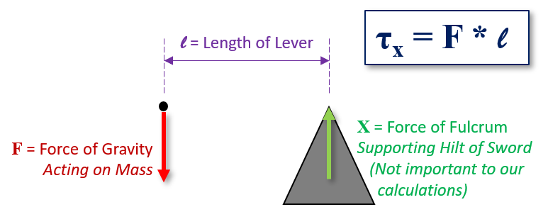
The convenient part of this is that you can measure anywhere. Since we are interested in the moment, and not the force, we can measure anywhere and come up with the same result. If you measure close to the tip you will get a low force and high length, if you measure closer to the cross you will get a high force and low length. Same final result.
Measuring Acceleration
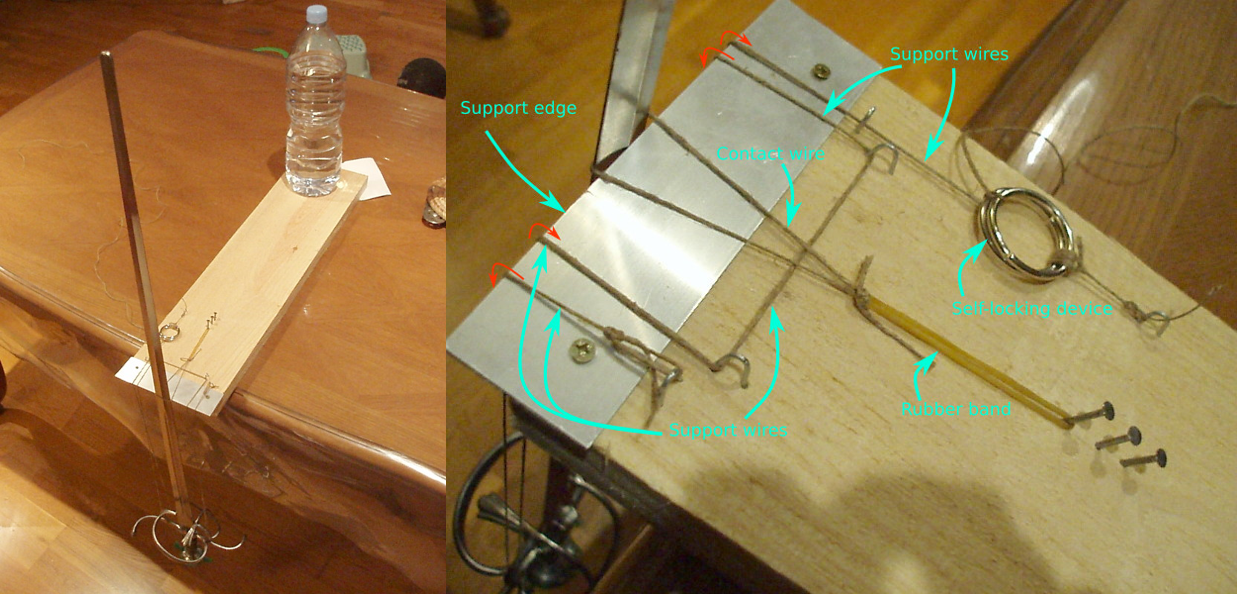
Measuring the acceleration of the sword was done using high speed footage of the sword falling. I set up the sword exactly as depicted in my free body diagram above, however the tip of the sword was held up by a thin string.
Once the string is cut, the sword begins to fall, and the acceleration of the blade calculated.
Put it all together we get a nice acceleration curve of the tip.
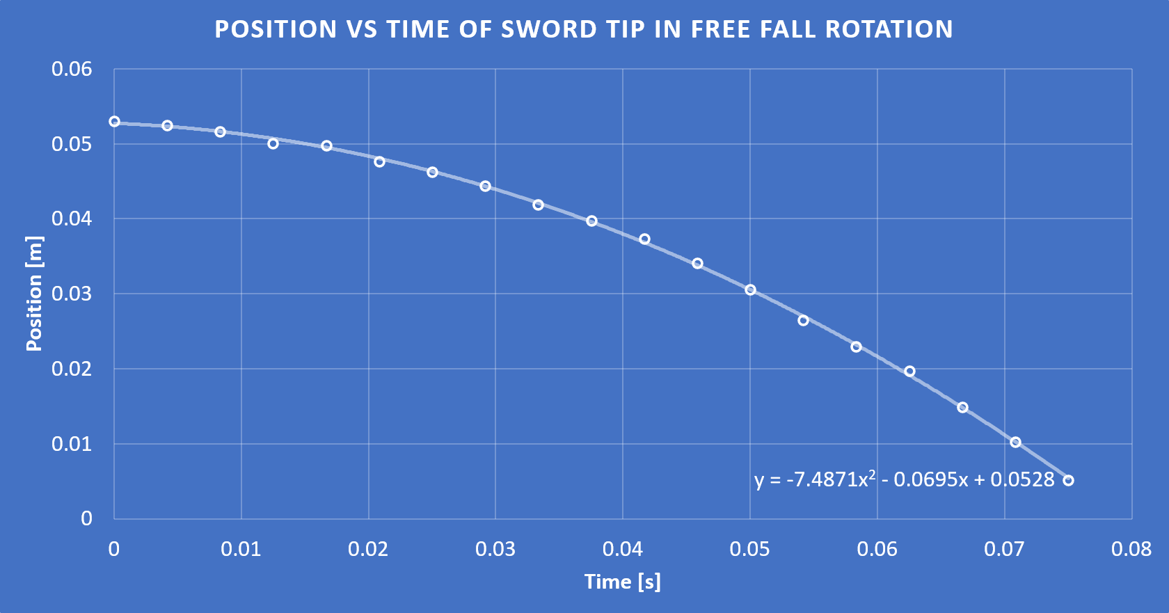
And bam! We have everything we need to get the moment of inertia.
Validation
Before I could rush out and test swords, I need to actually validate my method*. This is perfectly sound in theory, but would it produce a good result?
*Okay, I totally rushed out and tested a sword first. But I knew I couldn’t trust the results yet.
To test the method I purchased a 4 foot long iron pipe. Why? Because it is an object that is sword-like and has a known Moment of Inertia. Remember how I mentioned that there are pre-derived formulas for certain shapes? A long rod is one of those shapes. Just by knowing the mass and length I was able to calculate the Moment of Inertia.
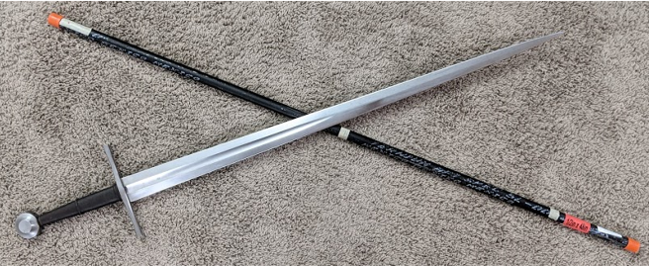
I performed the test twice, using two different pivot points to make sure my results were reproducible. The reproducibility was okay, not great, but there was other bad news.
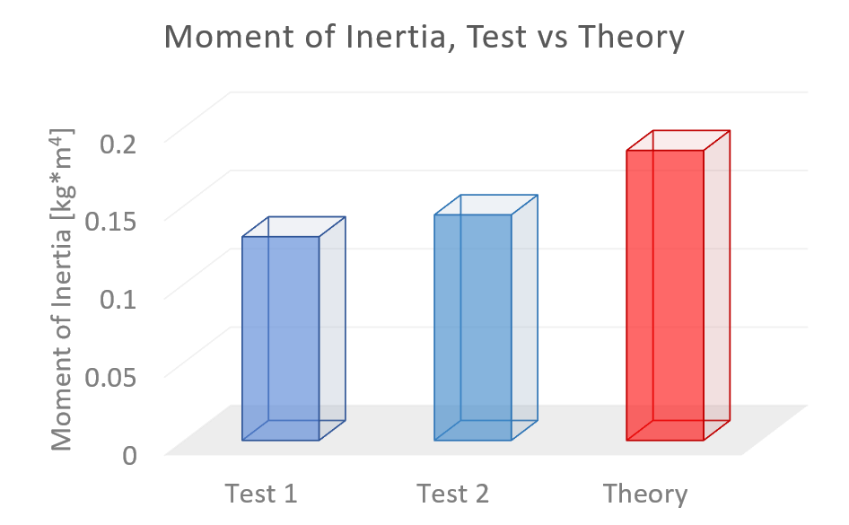
The method was not very close to the actual calculated value of the pipe. Which means that using this to actually get accurate results on swords is still just a pipe dream!
Conclusion
In conclusion I’m not going to be using this method anytime soon. I go into the details about exactly what went wrong below (it’s an intrinsic property of the camera field of view), and I have some ideas on how to change exactly how I do the measurement. But fortunately we have an existing and accurate method to use in the meantime. Time to start wrapping string in loops around nails!
Stuff for Nerds
Before we dive into sources of error, let’s think about what errors we are looking for. The test results all under-estimated the Moment of Inertia, which means that the sword was falling faster than expected.
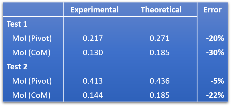
Note: The value I’m showing in the final results plot is the MoI around the Center of Mass. The values are calculated about the pivot point, and then transferred to the Center of Mass using the parallel axis theorem. Because this calculation reduces the experimental and theoretical by the same number, the percentage error is smaller for the calculation about the pivot. I’m still processing the full implications of this — if it is just a neat trick for hiding test error, or can be useful for sword dynamics, in that we almost never have a sword rotating about its center in the calculations.
Camera Distortion (1)
When looking at video footage, length can become distorted based on how far from the center of the camera you are. The same distance will become distorted, so that the same ‘length’ on the final video is different depending on if the object is in the center of the camera’s focus, or near the edge of the video.
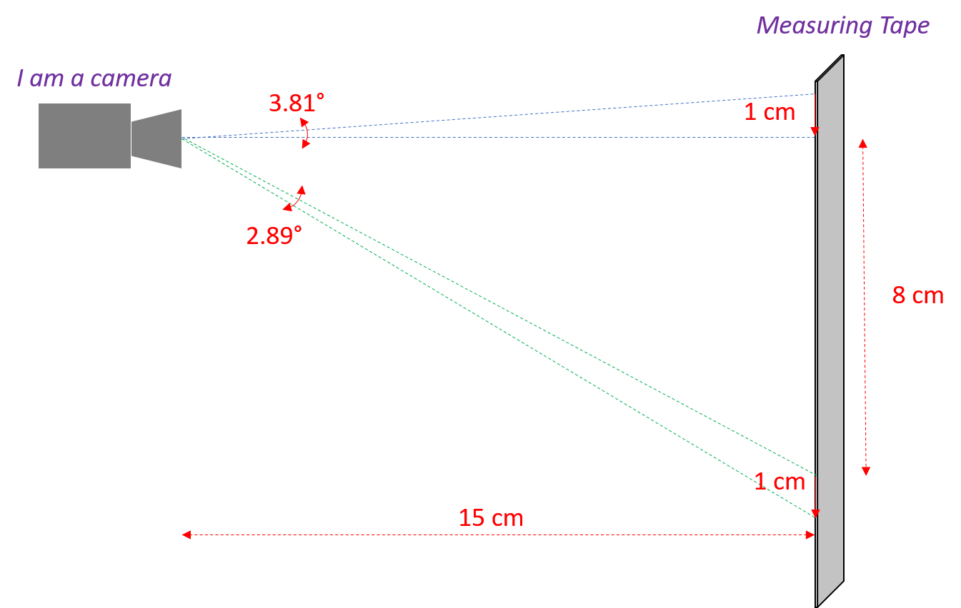
In theory you could calculate this easily with trigonometry, as I did in the diagram above. However modern cameras use a lot of fancy lens work and software correction to try to minimize this kind of thing, so it’s impossible to know how much of an effect it has. What I can do is check the final results.
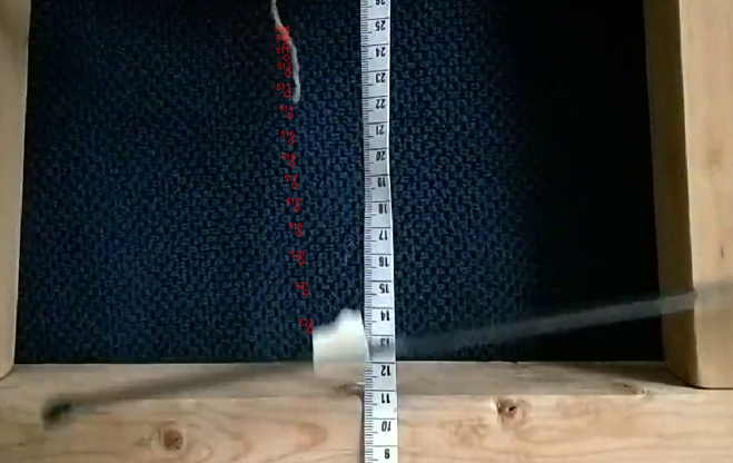
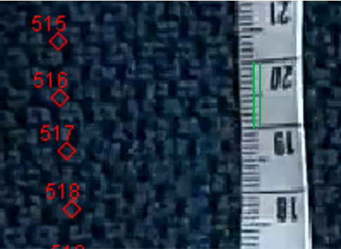
I inspected the measuring tape in the background to see that all of the tape measure markings were of a consistent interval. All results were within 3% of each other, and didn’t seem to have any discernible trend as I moved up or down the tape. And 3% is really bottoming out my ability to measure accurately with this resolution. In the image below you see ‘min’ and ‘max’ length line segments beside each other, which are well within my ability to resolve by eye.
Camera Distortion (2)
A known issue with using motion capture is due to the distance from the camera. This is the perspective effect, though it also presents itself based on lateral position. Even if two objects are the same horizontal distance from the camera, they are a different total distance. (Damn that Pythagoras!)
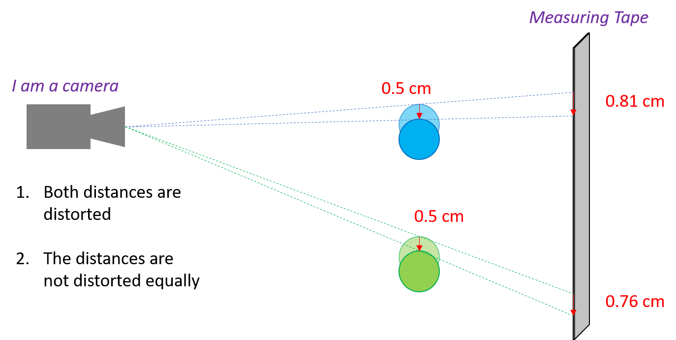
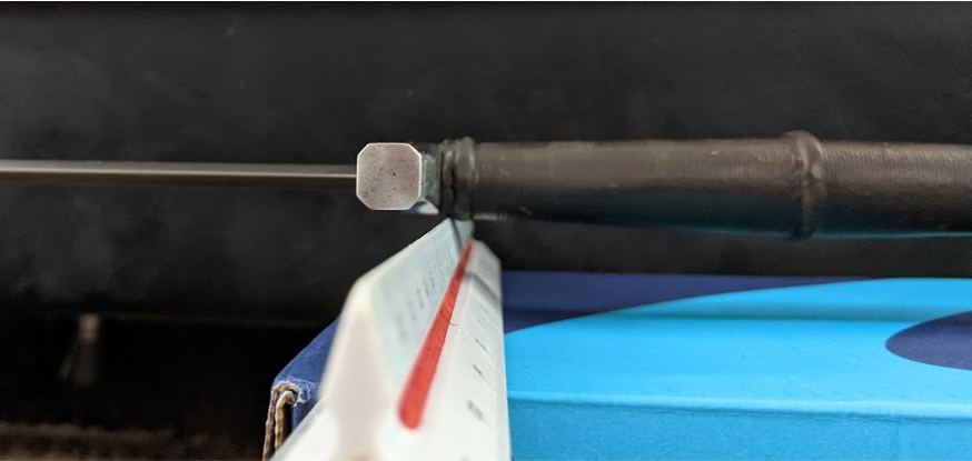
So what happens if I measure the thickness of the pipe, at the top and bottom of the drop?
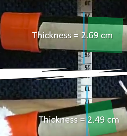
It looks like this is the culprit. I tried to keep the measuring tape extremely close to the pipe; however the pipe has its own thickness, distorting the view across its width! With the camera so close (for good resolution) this isn’t something correctable through simple experiment set up. Of course everything is solvable with more math, but that is way more post-processing than is reasonable. Especially if I want to be able to take measurements on a large number of swords.
So I have to make changes. I’m likely going to try to time the drop over a fixed distance, which allows me to escape the need to take measurements off the camera. I initially rejected this approach, because I figured there would be a frame or two where it would be ambiguous if it was falling or not. This would add an error factor to the final time measurement, but I think in the big picture that isn’t going to be consequential.