

The following is the Final Design Project prepared by Kristen Argyle, Michael Anderson, and Aundrea Hargroder for ECE 4710 in the Spring 2015 term. |
Abstract
Martial sports are a paradox – a compromise between safety and accuracy, especially when weapons-based martial arts are the basis for a martial sport. Weapons by their nature are dangerous and every step taken to make them more safe changes their essential characteristics. By design, safe weapon simulators make it less obvious when a fight-ending injury would have occurred. Thus, it is difficult to assess in martial sport how much the martial art is being applied and practiced. Using technology, this project has addressed that problem. This project integrated an embedded system that detects and reports martially sound strikes into a European Longsword simulator. This system filters out parries and contact too light to be considered valid while assessing the quality of a true strike. The entire system is contained within the sword simulator while disturbing its handling as little as possible.
Index Terms—force sensor, accelerometer, martial arts, martial sports, sabertron, contact assessment, rotational dynamics, force threshold, force sensor array, impact efficiency, sweet spot
I. INTRODUCTION
“IT’S A SWORD, said the Hogfather. THEY’RE NOT MEANT TO BE SAFE.” [1]
Use of electronics in martial sport is nothing new. Electric scoring was adopted for Olympic Fencing competition in 1936 [2]. Though fencing is virtually alone in its use of electronic scoring, numerous small studies and applications have been used in assessment of martial sport. Accelerometers and force sensors are an obvious choice to get a more objective estimate of an impact’s imparted force. Using such methods as a judging mechanism would be unnecessary for sports like boxing and mixed martial arts, since the winner is determined by who is left standing, roughly speaking. Spectators and judges don’t need a readout of the force behind a punch to determine if it did damage – the damage is there to see and the competitor will either carry on or succumb. With fencing, on the other hand, this option is not available as it is imitating a fight with weapons far more deadly than fists.
Some martial sports scale back the potential damage by imposing restrictions on competitions, allowed techniques, etc., but weapons-based martial sports are always bound by the safety imperative to introduce simulators for the weapons they train. In a competitive environment even weapon simulators can be dangerous, so safety equipment is also used. This is common sense preservation of life and limb, evident even historically in the use of wooden training weapons.
Enter modern European longsword competition and training [3]. Judges are still needed for competitions while honesty is necessary for friendly free-bouting. Both methods are prone to problems of subjectivity and human error, not to mention the constant monitoring that competitors must impose on themselves. Competitors have a twofold challenge in two directions: 1) did they receive a hit, 2) did they deliver a hit, and then both are multiplied by the question: was the hit seen/felt and counted? Our project aims to use technology to alleviate these problems.
II. BACKGROUND
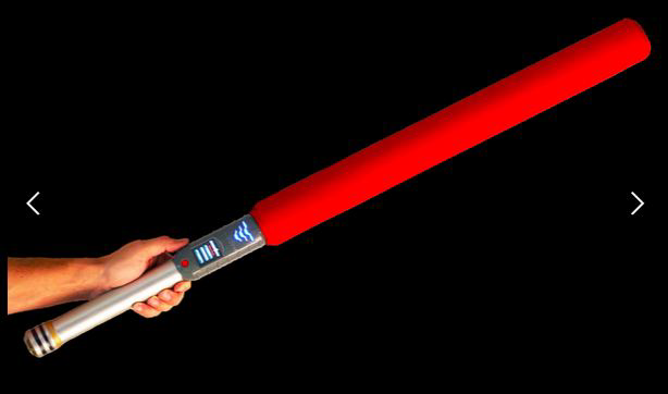
A company, LevelUp Inc., has already created a solution for counting sword hits. It is called ”Sabertron,” and it caters to the more casual field of foam sword fighting, a prototype of which can be seen in Fig. 1. Using components found in cell phones, the product discards detected hits to the opposing sword and counts hits to the body. All of this is contained in the sword [4]. For our project this was a convincing proof-of-concept for our own version which uses more rigorous sword simulators.
III. PROOF OF CONCEPT
In ECE 5780 Embedded Systems, we implemented the following basic requirements for our smart-sword system as a proof of concept:
- Hit detection
- Outward indication of hit detection
Our basic implementation consisted of two seperate systems, each with an acceleromter, an STM32F4 Discovery Board, an Arduino, a Piezo speaker, LEDs, and an RF tranceiver. This system lights a green LED when a hit is detected and plays a sound through the speaker.
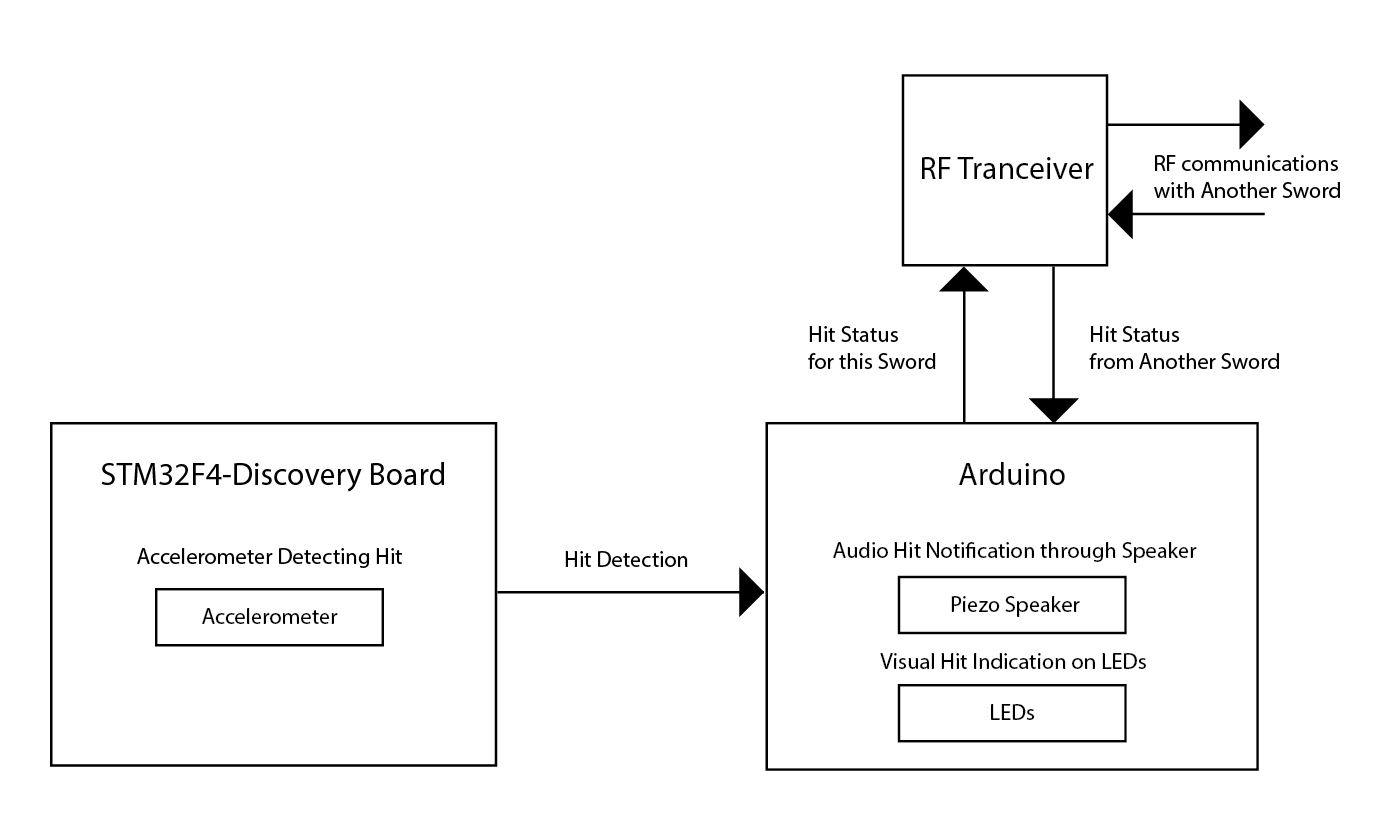
Additionally, the hit detection is communicated through the RF tranceiver to the other system. This allows for the detection of simultaneous hits, which mimics the action of two swords striking each other. When a simultaneous hit occurs, each system detects a hit and communicates it to the other, and the simultaneous hit is indicated with a red LED and a different sound through the speaker. This is a raw proof-of-concept for the most important parts of the project and is not the entirety of the base functionality we want for our Senior Project. The functional block diagram for our proof-of-concept design is shown in Fig.5.
IV. PROJECT WORK
The requirements that we originally planned implement for the Senior Project were:
- Assessment of quality of hit
- Discarding hits to opposing sword
- Upload and display of information off-sword
The primary goal of our smart-sword system is to enhance the training experience through automation while maintaining the integrity of authentic sword fighting. In order to achieve this goal we determined a priority list for the measurements and capabilities of this project.
The measurements this project prioritized were:
- Impact force
- Character of impact
The smart-sword capabilities this project prioritized were:
- Safety features preserved
- Handling features preserved
- Ruggedness of measurement equipment
- Sensitivity of measurement equipment
We chose to use accelerometers because they are small sensors which can easily fit within the body of a practice sword. Accelerometers are also very cost effective. We feel that accelerometers will provide the best data for performing hit detection analysis.
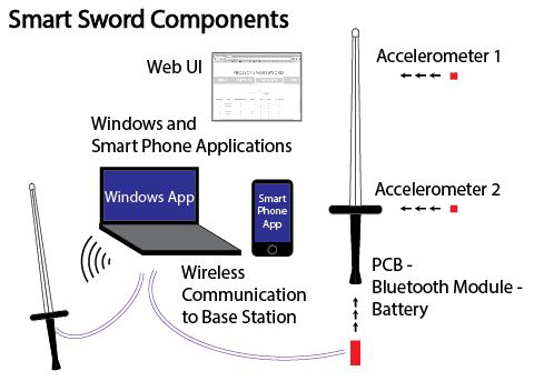
A graphical overview of the smart-sword design is shown in Fig. 3 below. The three main components of the project are the sword with sensing and communication ability itself, the server and application that interprets, displays, and communicates instructions to the swords, and the database and web UI that serve as information presentation to users.
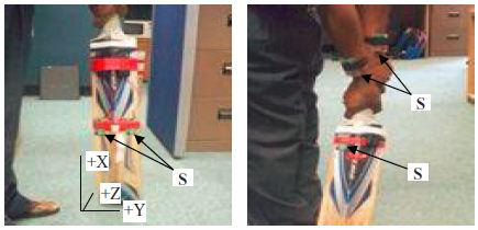
To address the issue of assessing hit quality we researched other projects which also addressed this issue. The point on a bat at which the most energy is transferred is often referred to colloquially as the ”sweet spot.” The less one’s hands feel rattled by an impact, the more efficient the energy transfer – and the less discomfort for the user. In a series of experiments with cricket bats, engineers used 3-axis accelerometers to detect the amount of lost energy, or ”jarring,” upon an impact in order to identify the sweet spot on a cricket bat [5]. Accelerometers were placed on both the wrists of the batter and on the bat, as pictured in Fig. 4.The data revealed that different parts of the bat indeed caused different wrist accelerations, and they were able to estimate the location of the sweet spot [5].
In the proof-of-concept design this hit detection was done with one accelerometer located on the STM32F4 Discovery board. In our final project we have two dedicated accelerometers at different locations to gather more sophisticated acceleration readings.
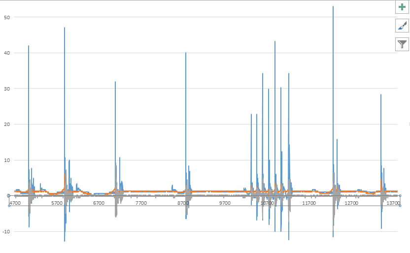
1) Hit Detection: For hit detection, we used two accelerometers in each sword. For our tests we found that hits usually show acceleration between 25 Gs and 100 Gs. An example of some rapid hit data can be seen in Fig. 5.
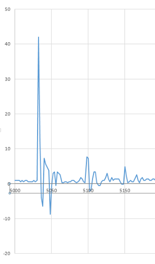
We chose a ADXL377 accelerometers for our project running in +/- 200G mode which proved to be more than sufficient for our needs. Using these accelerometers we can apply the concept from the cricket-bat study to our application to determine the quality of a hit. From a close up of a particular spike, we can confirm that there is one distinct peak for each strike (Fig 6).
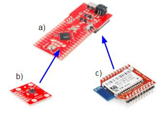
Both accelerometers are connected to anolog input pins on an Arduino Fio v3. The Arduino is also equipped with a RN42- XV Bluetooth Module.
The Arduino waits for the server application to establish a Bluetooth connection. The Arduino runs in two modes: capture mode and idle mode. In idle mode the Arduino simply waits for a command from the server over the Bluetooth connection. Commands are simply sent as a single byte over the Bluetooth socket. The commands which are utilized in our model only include the START command and the STOP command. The START command corresponds to a byte with the value 65 and the STOP command corresponds to a byte with the value 66. The START command puts the Arduino into capture mode and the STOP command puts the Arduino into idle mode.
In capture mode data from both the accelerometers on a sword is gathered from the Arduino. While in capture mode the Arduino continuously samples the ADC for each of the three axes of the two accelerometers and then immediately sends the data it sampled to the server application. When the Arduino ADC is sampled an integer between 0-1024 is returned which maps to a +/-200G reading by the accelerometer. The Arduino breaks the accelerometer ADC value for each axis into 2 bytes and sends each byte to the server over the Bluetooth socket. When the client receives a STOP command it acknowledges the end of the stream by sending the ASCII characters ”STOP”. This acknowledgment is required so that the server knows when to stop expecting data.
The server recombines the bytes and analyzes them as they are received for sudden changes in acceleration. If the server sees a sudden change in acceleration which exceeds 25G then the server assumes it has seen a hit on that sword. The 25G threshold was found through extensively testing our system. Once the server sees a hit from one sword it waits a small amount of time for the other sword to also report a hit before it takes any action. If within this wait time the server sees a hit on the other sword then the server assumes that the hits detected on each sword are a result of the two swords striking each other and counts the event as a parry. If, however, there is no hit reported by the second sword during this wait window, then the server assumes that the event must be a hit. When the server sees a hit then all of the accelerometer data for this hit is saved for post-event analysis. Post-event analysis introduced the challenge of maintaining our baseline functionality while transmitting data to an alternate location to be logged. To address this issue the server maintains a rolling queue of data for the purpose of reporting hit data. If the server sees a hit then it spawns a new thread and gives the new thread a copy of the rolling queue (which contains the data from the hit). The thread identifies which part of the data is related to the hit and logs the hit and it’s associated data to a database.
A. Base Simulator and Mounting System
If we had initially used a stick for testing and calibration and then moved to a sword, our numbers would have been off due to the fact that a sword is weighted and mass distributed differently than a hegemonic stick. Therefore, we performed all our testing and development on a nylon sword simulator of comparable weight and mass distribution to a real sword from Purpleheart Armory [7]. This simulator is in the same series used for HEMA tournaments [7] [8].
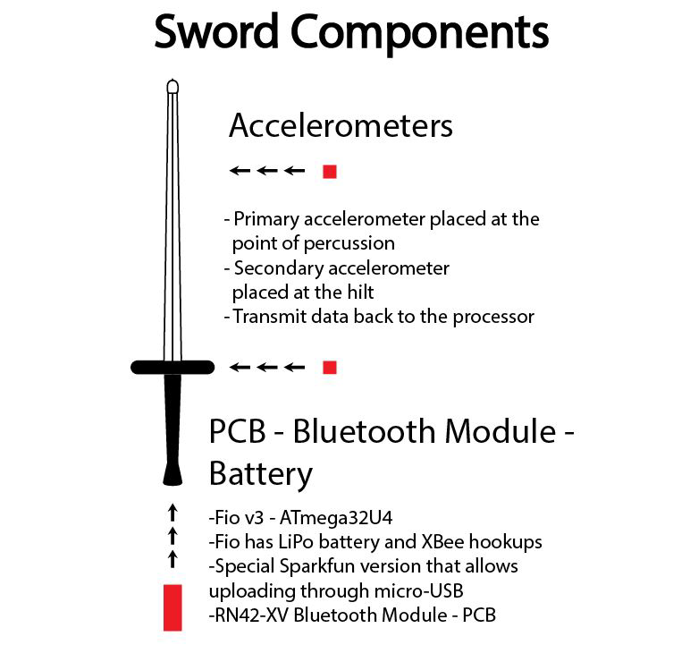
A high-level diagram of our mounting system can be seen in Fig. 7. One accelerometer is placed at the center of percussion, while the other rests near the hilt. The Arduino, Bluetooth module, and the battery are all located away from the sword proper in order to protect them and keep handling variations to a minimum.
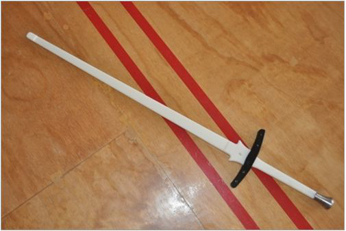
An example of the specific model of sword we chose can be seen in Fig. 8. We’ve chosen our simulator based on a few criteria. Already mentioned was weight and mass distribution as we want to preserve the integrity of a real sword’s handling, which lead us to the Pentti Type III series. The attachable hilt turned out to be unnecessary for our purposes, as we decided to avoid drilling into the sword.

We used mold-able plastic with a low melting point to fashion our case and mount. This plastic can be melted with a typical heat gun, but hardens at room temperature. Two bolts on either side of the sword and a plastic plate on the other side served to keep the case in place. The system already mounted can be seen in Fig. 10.
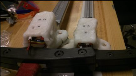
The Arduino Fio was mounted directly to the plastic via small bolts, using nuts to create space between the plastic and the components and accelerometer. We mounted the XBeeesque bluetooth module in the space on the Arduino Fio normally reserved for an XBee. The hilt accelerometer was soldered directly to the necessary pins. This allowed us to have all the components for the hilt in one case. The mounting plan can be seen in Fig. 11.
The center of percussion accelerometer was housed in its own plastic case, and the connections were directly soldered to a shrouded header for the crimped wire ribbon.
1) Hit Indication: The first form of hit indication performed by the smart-sword system was through LEDs placed on the hilt of the sword. In the final project hit determination is made by the server application. It is very simple to define an additional command in our Bluetooth communication protocol that would allow us to tell the sword to generate a notification indicating a hit. For our project we originally decided to have the sword generate hit indication but creating a system which could easily show hit indication was not implemented. We originally planned to place LEDs on the sword that would flash when a hit occurred, but the LEDs didn’t operate on a voltage that we could supply with our board. An additional transformer was required to power the LEDs. We opted to keep the sword footprint as small as possible and just perform hit indication on the server application. The server application keeps a scoreboard which updates as hits and parries are detected and also plays sounds when hits are detected.
2) Hit Assessment: In order for hits to have meaning, we must know if the sword hit another sword or if it hit a person. In our proof-of-concept solution we were able to make both swords communicate wirelessly with one another. We used RFID communication in this design. When one sword registered a hit, it was able to first confirm with the second sword. If the second sword also detected a hit, it registered the hit as sword-to-sword contact. If one sword did not register a hit and one did, it was counted as a hit to a person. We were very pleased to see this basic implementation work in the proof-of-concept design. However, the results were not always accurate – occasionally hits were misinterpreted.
We instead decided to remove the sword to sword communication and have both swords communicate with a server which could preform more advanced analysis of the data. However, the parry vs hit assessment method is almost the same as in the old sword to sword communication model.
This leaves open a gap – what if two people hit each other at the same time? The accelerometer data should spike differently for sword-to-sword contact than for sword-to-person contact. During our final project we attempted to analyze the data from our accelerometers to determine if the hit was against a sword or a person, but we weren’t able to reliably detect this information based on the accelerometer data alone. We opted to measure the time between accelerometer spikes in order to detect a parry vs a hit. We were able to reliably detect parries by looking for accelerometer peaks which occurred less than 50 ms apart. For two separate hits to be counted as a parry they would need to both occur during this small 50 ms window. We decided that this edge case probably occurs too rarely to worry about for our project scope.
B. Advanced Functionality
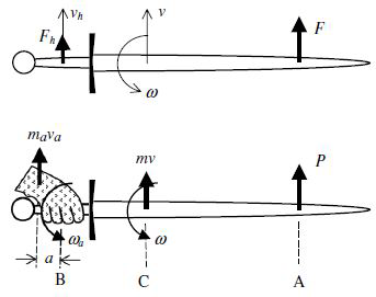
1) Hit Analysis: We originally planned to perform advanced hit analysis with our swords. In order to analyze hit efficiency, we needed at least two accelerometers: one to tell us the acceleration change measured at the center of percussion and another at the hand pivot node. By comparing these, we planned on analyzing the difference between an efficient strike and a light tap to get a rough estimate of the actual efficiency of the strike.
The data resolution we were able to obtain during the project however was very poor (approximately 1 sample per accelerometer axis per millisecond). Our server analyzes the acceleration of our hits to determine how hard the hit was. We were not able to perform any analysis concerning hit efficiency in our implementation, but we believe that such an analysis is possible with better resolution data and more time for studying the hit data. Simply comparing the ratio of acceleration between the hilt and the point of percussion should give some indication of how efficient the hit was, but we didn’t have time to implement such an analysis system during our project timeline.
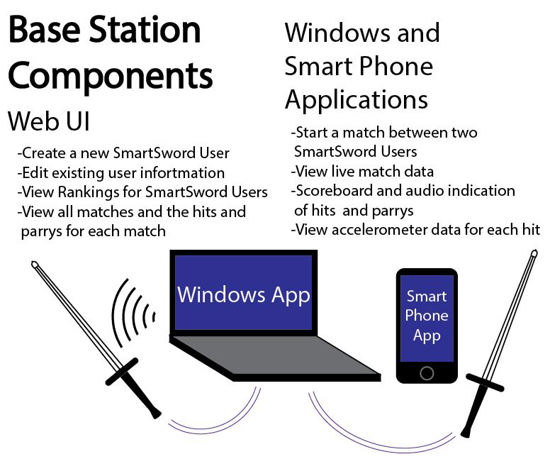
2) Interface: The main form of indication and assessment of hits were moved to the server and application. A high-level diagram of our base station can be seen in Fig. 13.
The server application stores all the data about hits it detects and matches it starts. If a hit or parry is detected the data is then sent to a MySQL database for long term storage where it can be analyzed. A RESTful API was developed using PHP for the purpose of managing data within our database. Because the server application must be run within Bluetooth range of the swords it becomes difficult to maintain a central database which contains all the information from matches. The RESTful API was developed to provide an interface for the server applications to read and write data in the database with a protocol which is not extremely sensitive to latency. The RESTful API allows applications to be written in any language and interact with our database. The server application integrates with the RESTful API and automatically starts matches and registers hits/parrys. As hits occur the server logs the accelerometer data in real time through the RESTful API.
3) Custom Boards: Ideally, component placement on the smart-sword would have been completely optimized. This means processors and non-sensor hardware could have been moved to a place subjected to less impact stress, while sensors could have easily been placed at specific nodes where the physics are easily calculated, known, and helpful. Due to its size, the STM32FR Discovery board from our original design is unwieldy and prone to being struck. We were able to shrink the footprint of our design with the Arduino Fio v3, but we hoped to shrink the footprint further by printing a board for our project. Time constraints didn’t allow for this to be completed. A custom shaped board (or boards) would have also been helpful in order to embed the system in the sword simulator without disturbing the sword’s shape or handling. This is mostly an advantage for mass modification or manufacture of the smart-sword system. We decided that for our project it would be best to stick with the Arduino and after developing a working system start to design a custom board.
A custom board for this project would likely fit a microprocessor, a Bluetooth module, and an accelerometer in as little space as possible. That way both accelerometers on the sword could communicate wirelessly, and multiple accelerometers could be mounted for research purposes.
C. Additional Features
1) Charger: The sword contains a rechargeable lithiumion battery. The sword can run off a micro USB connection or the rechargeable battery. The Arduino Fio v3 manages the battery charging. Unfortunately one of the limitations of our Arduino Fio v3 is that there is a switch which needs to be toggled when the battery is charging. Failure to toggle the switch connects the power from the USB and the battery and causes overvoltage on the Arduino Fio v3.
During our testing we found that the battery lasts several hours depending on how long the sword is actively capturing data.
2) Advanced Interface: Using the data logged into the SQL database we were able to create additional interfaces for interacting with data. We successfully developed a website which allows users to register themselves and keep track of all their matches and hit data. It also contains some fun features, such as a page for users to view their rankings amongst other smart-sword users. The database keeps track of the users, matches, and hits and associates all of this information so it can be easily retrieved.
3) Android Application: An Android application was developed for integration with our swords and the API. The application is capable of browsing match history and viewing hit/parry data as it is being logged. The Android application is also capable of pairing with the swords and starting a match. The Android application uses the aforementioned RESTful API to retrieve match and hit/parry data in addition to logging data about new matches and hits.
D. Project Issues
Our team ran into a number of issues during our project implementation. We felt that the biggest risk of our project was the physical strain placed on the electronics. Sabertron limited this strain by using foam swords. Since the material our swords are built from is less forgiving than foam, the physical strain on our electronic components was more significant. Accelerometers are designed to tolerate a certain level of impact stress, but given the somewhat chaotic environment of competition they may be subjected to more stress than intended.
The risk of breaking parts placed constraints on the mechanical design of our project. Parts need to be readily accessible and replaced should the worst happen. This meant parts needed to be attached with a method of extraction that doesn’t damage the sword. A large portion of our time in this project was spent on developing a reliable functional case for our embedded system which addressed these concerns.
During initial testing of the Bluetooth data logging our team noticed that we were not detecting some of our hits. Further investigation led us to find that we were getting samples from the Arduino at a very slow rate. We were initially getting approximately 300-400 samples per axis per second for a single accelerometer. We solved this issue by increasing our Bluetooth baud rate from the default value of 9600 to 115200. This change increased the number of samples we were getting to approximately 1500 samples per axis per second for a single accelerometer. Originally our code was also sending the ADC values as ASCII delimited by commas. We changed the code to send raw bytes instead of ASCII. After this change we started to receive 2000 samples per axis per second for a single accelerometer. After adding our second accelerometer to the Arduino we started receiving 1000 samples per axis per second for 2 accelerometers.
After the change to the way acceleration data was sent, we started to notice another issue with our server. Occasionally, the data we received started to not make sense. The values being received were too large to have come from the Arduino ADC (values outside the 0-1024 range that the ADC provides). We noticed that the invalid data that we were receiving made sense if we processed the bytes in the reverse order. Because our application receives bytes 2 at a time and combines them it requires that we receive every byte in order from our Arduino. Debugging was difficult, as the very process of interrupting the program caused interruptions to the byte stream. However, we determined that the bytes were being lost because the socket buffer was overflowing. The issue occurred most often when registering a hit because notification of the controller function would delay the serial monitor code enough to cause the socket buffer to overflow. We extended the size of the socket buffer and made hit logging run on a separate thread to address this problem.
We originally planned to analyze what kind of hit was made – cut, thrust, slice – but this analysis logic was not implemented in our project. The slow sampling rate of our sword makes this kind of analysis very hard. We also noticed that a hit which visually appeared to be made along a single axis (e.g. a hit which was made directly against the edge of the blade), would also produce large spikes in acceleration in other axes of the sword. This made analysis of how the sword was contacted extremely difficult if not impossible with more advanced data.
Since our project goes beyond all-real-time functionality, we needed to consider the risks of creating additional data logging and analysis systems for post-event assessments. We run the risk of bogging down the speed of the real-time system by preserving information. We feared that navigating this hazard may end up taking too much time and effort and cause potential overhauls of our system. Fortunately, our decision to offload the data analysis to a server allowed for this information to be easily logged over the RESTful API on a separate thread when a hit was detected by the real time analysis.
We thought to add GPS data logging to our sword during our project planning. The GPS module would allow us to very accurately synchronize time on the device so that it is able to better correlate data with the other sword. However, because swords are no longer communicating with each other in our new design it wasn’t necessary to have time between the swords accurately synchronized. We also had the idea that we might want to track teams of users simultaneously. The GPS data would have been used to tell us which users were in immediate proximity of each other, so we could determine which combatants were currently engaged. Unfortunately the precision of consumer GPS made this goal fairly impossible. As a result we did not implement any GPS capabilities into our project.
V. PROJECT RESOURCES
TABLE I PARTS USED IN PROJECT
- Fio v3 – ATmega32U4
- RN42-XV Bluetooth Module
- Nylon Practice Longsword
- 2 ADXL377 Accelerometers
- 5v Lithium ion battery and charger .
REFERENCES
- [1] T. Pratchett, Hogfather. Victor Gollancz, 1996.
- [2] (2015) Fencing. [Online]. Available: http://www.britannica.com/ EBchecked/topic/204172/fencing/2263/Organized-sport
- [3] M. W. Bishop, “Medieval weapon finds modern appeal,” New York Times, 2014, 15 September. [Online]. Available: http://nyti.ms/1uBcsWD
- [4] T. R. D. Lynch, J. Davidson. (2015). [Online]. Available: http: //sabertron.com/
- [5] A. K. Sarkar, D. A. James, A. W. Busch, and D. V. Thiel, “Cricket bat acceleration profile from sweet-spot impacts,” Procedia Engineering, vol. 34, no. 0, pp. 467 – 472, 2012, fENGINEERINGg fOFg fSPORTg fCONFERENCEg [Online]. Available: http: //www.sciencedirect.com/science/article/pii/S1877705812016931
- [6] M. Denny, “Swordplay: an exercise in rotational dynamics,” European Journal of Physics, vol. 27, no. 4, p. 943, 2006. [Online]. Available: http://stacks.iop.org/0143-0807/27/i=4/a=025
- [7] (2015) Type iii federschwert longsword plastic guard 1. [Online]. Available: http://www.woodenswords.com/product p/type-iii-f-pg1.htmr
- [8] (2015, 18 April) Study in steel. [Online]. Available: https://www. facebook.com/events/381670271994783/r